
Reference
ESP32-S3 Zero / Super Mini Pinout
The real pin reference for the ESP32-S3-Zero-style board: a coin-sized ESP32-S3 devkit sold under names like "ESP32-S3 Zero" and "ESP32-S3 Super Mini" by Waveshare and several other sellers.
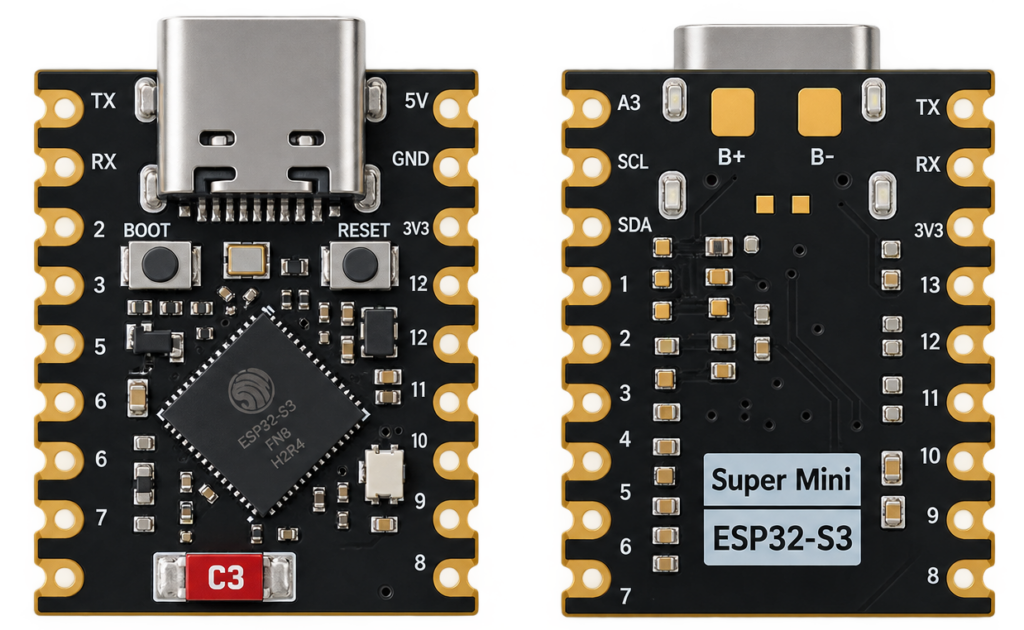
Boards sold as “ESP32-S3 Zero” or “ESP32-S3 Super Mini” are near-identical coin-sized ESP32-S3 breakouts from several sellers, Waveshare’s own ESP32-S3-Zero is the most established and best-documented version, this guide is sourced from Waveshare’s own documentation. If your specific board came from a different seller, double-check its silkscreen labels against the table below before wiring anything, minor differences between clones are common.
System-on-chip and board
Built around the same ESP32-S3 chip as this site’s AI-S3 board: dual-core Xtensa LX7, Wi-Fi 802.11 b/g/n, Bluetooth 5 LE, native USB. This specific board is 23.5×18mm, single USB-C port, an onboard WS2812 addressable RGB LED, a BOOT button, and 4MB flash with 2MB of quad-SPI PSRAM (must be explicitly enabled in firmware, it isn’t used automatically).
GPIO reference
| GPIO | Function | Notes |
|---|---|---|
| 0 | BOOT button | Hold low while connecting USB to enter download mode |
| 1, 2, 4–8, 15–18, 38 | General-purpose, ADC-capable | 12 pins with no boot/system duties, safe first choice for your own wiring |
| 3, 9–14 | Strapping pins | Configure boot behavior at reset, avoid unless you know what you’re changing |
| 21 | WS2812 RGB LED | Onboard, addressable status LED |
| 33–37 | Not exposed | Reserved internally for octal PSRAM, not broken out to a header pin at all on this board |
| 39–42 | JTAG (TCK/TDO/TDI/TMS) | Usable as plain GPIO if you don’t need hardware debugging |
| 43, 44 | UART0 TX/RX | To onboard USB-serial converter |
| 45 | Strapping (flash voltage) | Avoid driving externally at power-on |
Real gotchas
- GPIO33–37 genuinely don’t exist on this board’s header, even though the ESP32-S3 chip itself has them, they’re wired internally to the onboard PSRAM. Don’t design around them being available, unlike some other ESP32-S3 boards that do expose them.
- PSRAM isn’t automatic. The 2MB of onboard PSRAM only becomes usable once your build explicitly enables it (in Arduino IDE: Tools → PSRAM → “OPI PSRAM”; in ESP-IDF: the relevant `menuconfig` option).
- Seller variation. Because “ESP32-S3 Zero” and “ESP32-S3 Super Mini” aren’t a single manufacturer’s trademarked product, always check your specific board’s silkscreen against this table rather than assuming an exact match.
Conclusion
This is the smallest, cheapest way to get a full ESP32-S3 with native USB and PSRAM onto a breadboard. For a larger board with dual USB-C and a built-in USB-serial adapter dedicated purely to flashing, see the AI-S3.
Related
 Reference
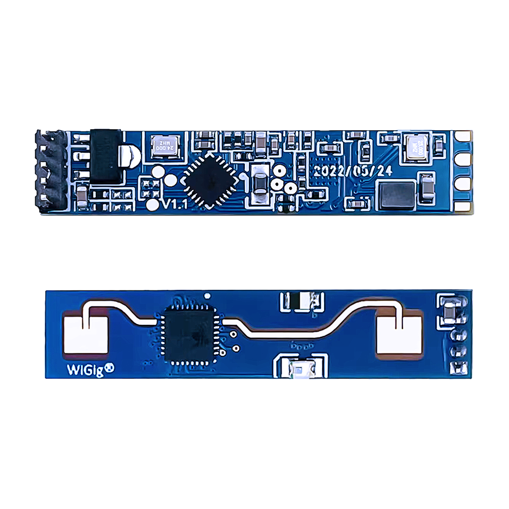
The Complete Guide to the HLK-LD2410 24GHz Human Presence Radar Module
A 24 GHz FMCW radar that detects stationary presence, breathing and micro-motion, not just movement, which is exactly where a standard PIR sensor fails. This guide covers the UART/OUT-pin pinout, ESP32 wiring, configurable distance gates, and ESPHome integration.
Read more
Reference
The Complete Guide to the HLK-LD2410 24GHz Human Presence Radar Module
A 24 GHz FMCW radar that detects stationary presence, breathing and micro-motion, not just movement, which is exactly where a standard PIR sensor fails. This guide covers the UART/OUT-pin pinout, ESP32 wiring, configurable distance gates, and ESPHome integration.
Read more
 Guide
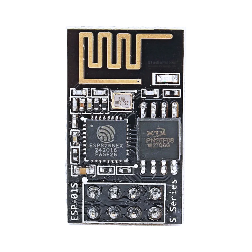
ESP8266-01 Pinout
The complete pin reference for the ESP8266-01 breakout: just 8 pins, only 2 usable GPIOs, and no onboard USB, so wiring it up needs a bit more care than a dev board.
Read more
Guide
ESP8266-01 Pinout
The complete pin reference for the ESP8266-01 breakout: just 8 pins, only 2 usable GPIOs, and no onboard USB, so wiring it up needs a bit more care than a dev board.
Read more
 Guide
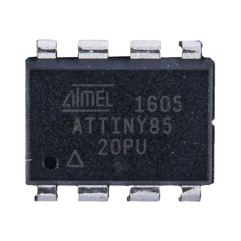
ATtiny85 Pinout
The complete pin reference for the ATtiny85: an 8-pin AVR chip with 6 GPIOs, 3 ADC channels, and no onboard USB, so it’s programmed over ISP rather than plugged straight into a computer.
Read more
Guide
ATtiny85 Pinout
The complete pin reference for the ATtiny85: an 8-pin AVR chip with 6 GPIOs, 3 ADC channels, and no onboard USB, so it’s programmed over ISP rather than plugged straight into a computer.
Read more
More guides
Keep building.
From ESP32 HomeKit accessories to Arduino and ATtiny reference guides, there’s more where this came from.
All guides