
Reference
ESP32-CAM (AI-Thinker) Pinout
The real pin reference for the AI-Thinker ESP32-CAM: an ESP32 with a camera connector and microSD slot, and only 2 or 3 genuinely free GPIOs left over.
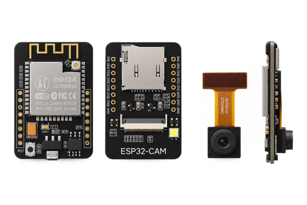
The ESP32-CAM pairs an ESP32 with an OV2640 camera and a microSD slot on one small board. It’s an extremely popular, extremely cheap way to add a camera to a project, and also one of the most commonly miswired boards, most of its GPIOs are already committed to the camera or SD card before you connect anything of your own.
No onboard USB, and how to flash it
This board has no onboard USB-to-serial converter. Unlike this site’s other ESP32 devkits, you need a separate external FTDI (or similar USB-to-serial) adapter wired to its UART pins to flash it or view serial output at all. Even with an adapter connected, you must also connect GPIO0 to GND before powering on or resetting the board to enter flashing mode, then disconnect it and reset again to run your uploaded firmware normally. Power it from a real 5V source, several guides note the board can behave unreliably on 3.3V despite the pin being labeled 3.3V-tolerant.
Camera pins (not available for other use)
These GPIOs are wired directly to the onboard OV2640 camera and are not available as general-purpose I/O:
| GPIO | Camera signal |
|---|---|
| 0 | XCLK |
| 5 | Y2 (data) |
| 18, 19, 21, 22, 23, 25, 26, 27 | Remaining data lines, PCLK, VSYNC, HREF |
| 26 | SIOD (camera I²C data) |
| 27 | SIOC (camera I²C clock) |
| 32 | Camera power-down |
The rest of the GPIOs
| GPIO | Function | Notes |
|---|---|---|
| 0 | Camera XCLK, boot strap | Pulled up 10kΩ; connect to GND to enter flash mode |
| 1 | UART TX | To your external FTDI adapter |
| 3 | UART RX | From your external FTDI adapter |
| 2, 12, 13, 14, 15 | SD card (1-bit or 4-bit mode) | Free for general use only if the SD card is disabled or set to 1-bit mode |
| 4 | Onboard flash LED, SD DATA1 | Inverted logic on some boards; shares a pin with the SD card’s 4-bit mode |
| 16 | PSRAM chip select | Internally connected, do not use as an input, this is a common source of random crashes |
| 33 | Onboard red LED | Inverted logic: LOW turns it on |
Genuinely free GPIOs, with the camera enabled and the SD card either disabled or in 1-bit mode: GPIO 2, 4, 12, 13, 14, 15 (GPIO4 only if you don’t need the onboard flash LED). That’s the entire realistic budget of free pins on this board, plan accordingly.
Conclusion
The ESP32-CAM is genuinely the cheapest way to add a camera to an ESP32 project, but budget your wiring around 2–6 free GPIOs, not the ESP32’s full pin count, and remember the external FTDI adapter, it isn’t optional. For a camera-equipped ESP32-S3 board with a display instead, see the T-Display-S3 (display, not camera) or Seeed’s XIAO ESP32S3 Sense (camera connector, no display).
Related
 Guide
ESP32-C6-WROOM-1 Pinout
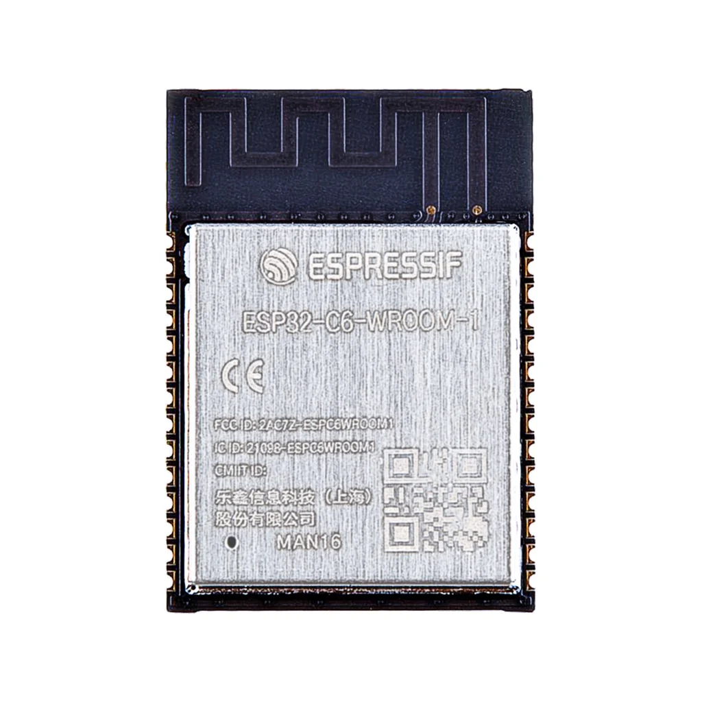
The complete pin reference for the ESP32-C6-WROOM-1 module: Wi-Fi 6, Bluetooth LE and 802.15.4 (Thread and Zigbee) on one chip, plus the exact pins you can safely reuse.
Read more
Guide
ESP32-C6-WROOM-1 Pinout
The complete pin reference for the ESP32-C6-WROOM-1 module: Wi-Fi 6, Bluetooth LE and 802.15.4 (Thread and Zigbee) on one chip, plus the exact pins you can safely reuse.
Read more
 Reference
Seeed Studio XIAO nRF52840 Pinout
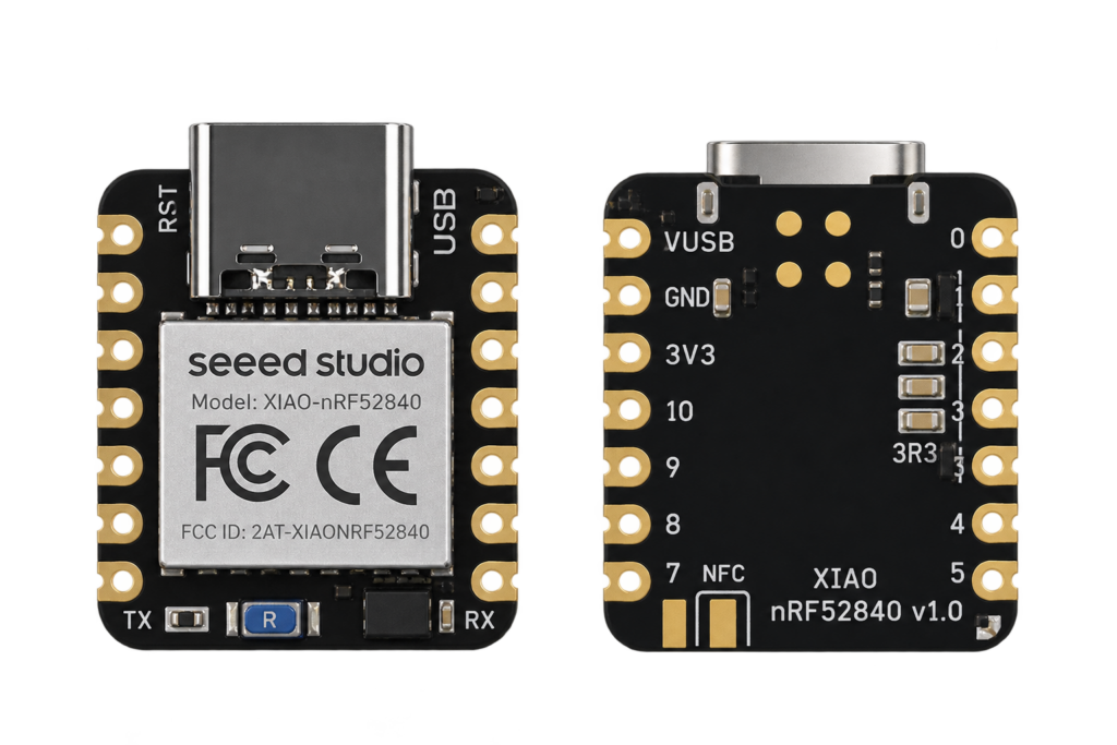
This site's first non-Espressif board: Nordic's nRF52840 Bluetooth Low Energy SoC on Seeed's thumbnail-sized XIAO carrier, with no Wi-Fi radio at all.
Read more
Reference
Seeed Studio XIAO nRF52840 Pinout
This site's first non-Espressif board: Nordic's nRF52840 Bluetooth Low Energy SoC on Seeed's thumbnail-sized XIAO carrier, with no Wi-Fi radio at all.
Read more
 Reference
The Complete Guide to the 1.28-Inch GC9A01 Round TFT Display Module
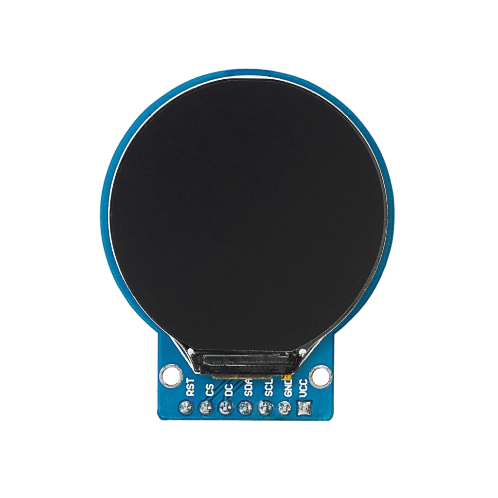
A 240x240 round IPS display driven by the GC9A01 controller over SPI, ideal for clocks, gauges and wearables. This guide covers the pinout, ESP32 wiring, and example code with both Adafruit_GC9A01A and TFT_eSPI.
Read more
Reference
The Complete Guide to the 1.28-Inch GC9A01 Round TFT Display Module
A 240x240 round IPS display driven by the GC9A01 controller over SPI, ideal for clocks, gauges and wearables. This guide covers the pinout, ESP32 wiring, and example code with both Adafruit_GC9A01A and TFT_eSPI.
Read more
More guides
Keep building.
From ESP32 HomeKit accessories to Arduino and ATtiny reference guides, there’s more where this came from.
All guides