
Reference
AI-S3 Pinout
The pin reference for the AI-S3, an ESP32-S3-WROOM-1 development board with dual USB-C, native USB and an onboard addressable RGB LED.
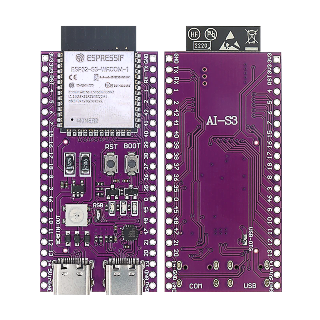
The AI-S3 is an ESP32-S3 development board: dual USB-C ports, an onboard WS2812 RGB LED, and a full GPIO breakout on a compact board. This site’s AI-C3 board covers the same family’s RISC-V sibling, this is the Xtensa LX7, AI-accelerated version. This guide covers the AI-S3’s real pinout: what’s confirmed from the board’s own documentation, and what needs checking against Espressif’s own ESP32-S3 datasheet before you rely on it.
System-on-chip and module
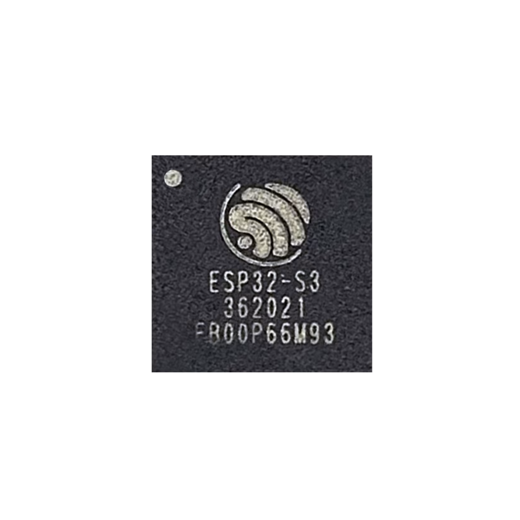
The ESP32-S3 is Espressif’s dual-core, 240MHz Xtensa LX7 chip, with Wi-Fi 802.11 b/g/n, Bluetooth 5 (LE), and vector instructions aimed at edge-AI workloads (face/audio detection).
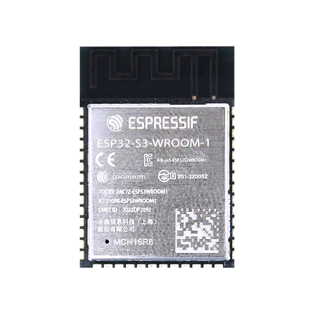
The board is built on the ESP32-S3-WROOM-1 module: flash, PSRAM, crystal and antenna in one shielded package.
The AI-S3 dev board breaks the module’s GPIOs out to a labeled header, adds BOOT and RESET buttons, two USB-C connectors (one for flashing, one for native USB OTG), and an onboard WS2812 RGB LED for status feedback, all on a compact purple PCB.
Key features
- Dual-core 240MHz Xtensa LX7
- Wi-Fi 802.11 b/g/n, Bluetooth 5 LE
- Native USB (device and host/OTG)
- 14 capacitive touch GPIOs
- Two 12-bit ADCs
- Up to 20 PWM-capable channels
- SPI, UART, I²C, I2S, RMT
- Secure boot and flash encryption support
- Onboard WS2812 RGB LED on GPIO48
GPIO quick reference
The pins this board’s own documentation calls out specifically, not an exhaustive list of every GPIO the ESP32-S3-WROOM-1 module exposes, check Espressif’s own ESP32-S3 datasheet for the complete pin map before a board-spanning design.
| GPIO | Function | ADC | Touch | Notes |
|---|---|---|---|---|
| 0 | BOOT strap, touch | No | Yes | Hold low at reset to enter flash mode |
| 1–10 | ADC1, several also touch | Yes | Yes (0–13 range) | |
| 8 | I²C SDA (suggested default) | Yes | Yes | Remappable with Wire.begin(SDA, SCL) |
| 9 | I²C SCL (suggested default) | Yes | Yes | Remappable |
| 19 | USB D+ | No | No | Native USB, avoid using as plain GPIO |
| 20 | USB D− | No | No | Native USB, avoid using as plain GPIO |
| 34 | SPI CS (suggested default) | No | No | |
| 35 | SPI MOSI (suggested default) | No | No | |
| 36 | SPI CLK (suggested default) | No | No | |
| 37 | SPI MISO (suggested default) | No | No | |
| 43 | UART0 TX | No | No | To onboard USB-serial, to your PC |
| 44 | UART0 RX | No | No | From onboard USB-serial, from your PC |
| 48 | WS2812 RGB LED | No | No | Built-in, addressable |
Avoid ADC2 (GPIO11–20) while Wi-Fi is active, the two share internal resources and readings can be unreliable during a Wi-Fi connection.
Programming
Any of Arduino IDE (with ESP32-S3 board support), PlatformIO, or ESP-IDF works. The left-hand USB-C port is the one wired to the onboard USB-serial converter, used for flashing and the serial monitor. The second USB-C port is the ESP32-S3’s own native USB, usable as a USB host or device once your firmware sets that up.
| Function | Pin | Description |
|---|---|---|
| TXD0 | GPIO43 | Serial output to PC |
| RXD0 | GPIO44 | Serial input from PC |
| BOOT | GPIO0 | Hold low during upload if it doesn’t start automatically |
| EN | EN pin | Resets the chip |
Conclusion
The AI-S3 gives you the ESP32-S3’s extra compute, native USB and touch/AI capabilities in a breadboard-friendly board with a built-in USB-serial adapter, no separate programmer needed. For a lower-power, cheaper RISC-V alternative from the same board family, see the AI-C3. Need something smaller instead? See the coin-sized ESP32-S3 Zero or Seeed’s XIAO ESP32S3.
Related
 Reference
MPU6050 Accelerometer + Gyroscope Complete Guide
The MPU6050 packs a 3-axis accelerometer and 3-axis gyroscope on one die with an onboard motion-fusion processor, for around the price of a single sensor. This guide covers its real I2C addressing, pinout, and wiring one to an ESP32.
Read more
Reference
MPU6050 Accelerometer + Gyroscope Complete Guide
The MPU6050 packs a 3-axis accelerometer and 3-axis gyroscope on one die with an onboard motion-fusion processor, for around the price of a single sensor. This guide covers its real I2C addressing, pinout, and wiring one to an ESP32.
Read more
 Guide
ESP32-S2 Mini Pinout
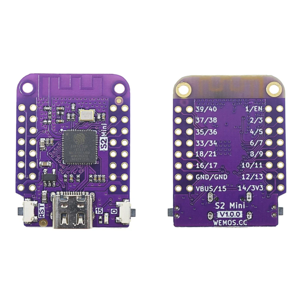
The complete pin reference for the WEMOS/Lolin S2 Mini: native USB, 14 capacitive touch pins, and no Bluetooth at all.
Read more
Guide
ESP32-S2 Mini Pinout
The complete pin reference for the WEMOS/Lolin S2 Mini: native USB, 14 capacitive touch pins, and no Bluetooth at all.
Read more
 Reference
MCP23017 16-Bit I/O Expander – Complete Guide
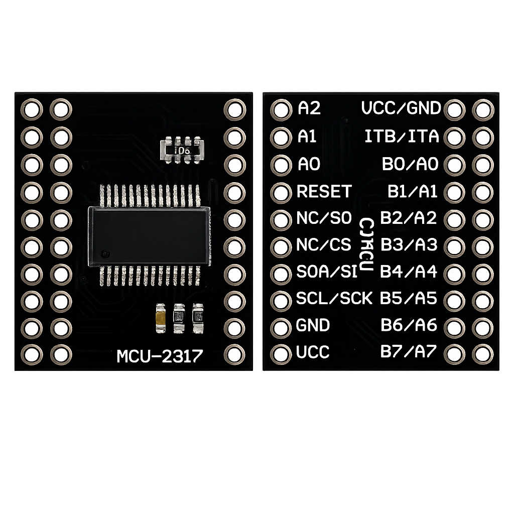
Add 16 fully-configurable GPIO pins to a pin-limited board over a two-wire I²C bus, with per-pin pull-ups and interrupt-on-change built in. This guide covers the pinout, I²C address selection, register map, ESP-IDF/Arduino code, and how it compares to the simpler PCF8574.
Read more
Reference
MCP23017 16-Bit I/O Expander – Complete Guide
Add 16 fully-configurable GPIO pins to a pin-limited board over a two-wire I²C bus, with per-pin pull-ups and interrupt-on-change built in. This guide covers the pinout, I²C address selection, register map, ESP-IDF/Arduino code, and how it compares to the simpler PCF8574.
Read more
More guides
Keep building.
From ESP32 HomeKit accessories to Arduino and ATtiny reference guides, there’s more where this came from.
All guides