For the hobby developer who wants full control over their smart hardware, the Aubess Power Monitor Switch is an excellent starting point. It is an inexpensive Wi-Fi power switch with built-in energy monitoring, solid hardware, and a compact design. Under the hood, however, the device uses a closed Wi-Fi module based on a ESP-02S (or a similar variant). While functional, this chip is poorly supported by open-source tooling, heavily cloud-oriented, and difficult to customize or maintain long-term.
In this step-by-step guide, we convert the Aubess Power Monitor Switch into a fully open-source, locally controlled smart power monitor by:
- Removing the original Wi-Fi module
- Installing an ESP8685-WROOM-03
- Adding ESP32 Lifecycle Manager (LCM)
- Installing the ESP32 Power Monitor Switch firmware via LCM
- Explaining all firmware features, including HomeKit, power monitoring, wall-switch logic, and recovery
The goal is simple: a fully self-controlled, firmware-owned power monitor switch — without proprietary code, cloud dependency, or artificial limitations.
Why Modify This Smart Switch?
There are more smart devices than ever — but not all of them truly belong to you. Most budget IoT devices depend on:
- Cloud servers
- Vendor accounts
- Proprietary mobile apps
- Remote infrastructure
- Unknown data collection
This creates the privacy trap: you buy the device, but the manufacturer controls it.
If you want to understand the deeper implications of cloud-based IoT products, read:
https://www.studiopieters.nl/why-you-should-or-shouldnt-buy-a-smart-plug-from-action
By replacing the firmware and Wi-Fi module, you regain:
- Full privacy
- Local device control
- Firmware ownership
- Offline operation
- No telemetry
- Long-term independence
Difficulty Level
Rating: 2 / 5 Soldering Irons – Beginner friendly

This project is beginner-friendly, provided you are comfortable with:
- Desoldering and soldering
- Working with small SMD components
- Using a serial flasher
- Command-line tools
No advanced electronics background is required.
⚠️ HIGH VOLTAGE WARNING
⚡ DANGER: MAINS ELECTRICITY CAN KILL
This project involves a device that connects directly to 230 V AC.
- Always unplug before opening
- Never work on a live device
- Use insulated tools
- Avoid touching exposed conductors
Proceed only if you understand the risks involved. The author accepts no liability for damage, injury, or accidents. If in doubt — consult a licensed electrician.
Hardware Overview
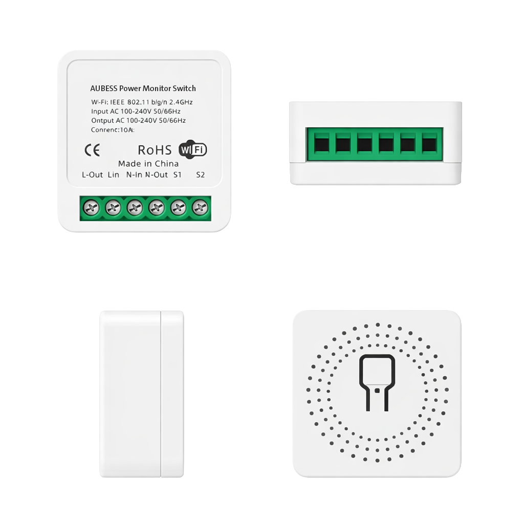
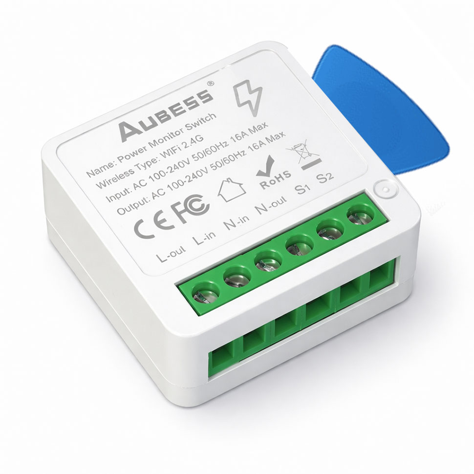
Product: Aubess Power Monitor Switch
Voltage: 220–240 V~ 50/60 Hz
Maximum load: 16 A / 3680 W
Internally, the device consists of:
- A mains-rated relay
- A BL0942 energy-measurement IC
- A closed-source Wi-Fi module (to be replaced)
The hardware itself is solid — the firmware ecosystem is the limiting factor.
Why Replace the Original Wi-Fi Module?
Depending on the revision, the Aubess switch uses a closed ESP02S-style or BK7231-based module. These chips suffer from:
- Cloud dependency
- Limited OTA update support
- Poor recovery options
- Weak open-source ecosystem
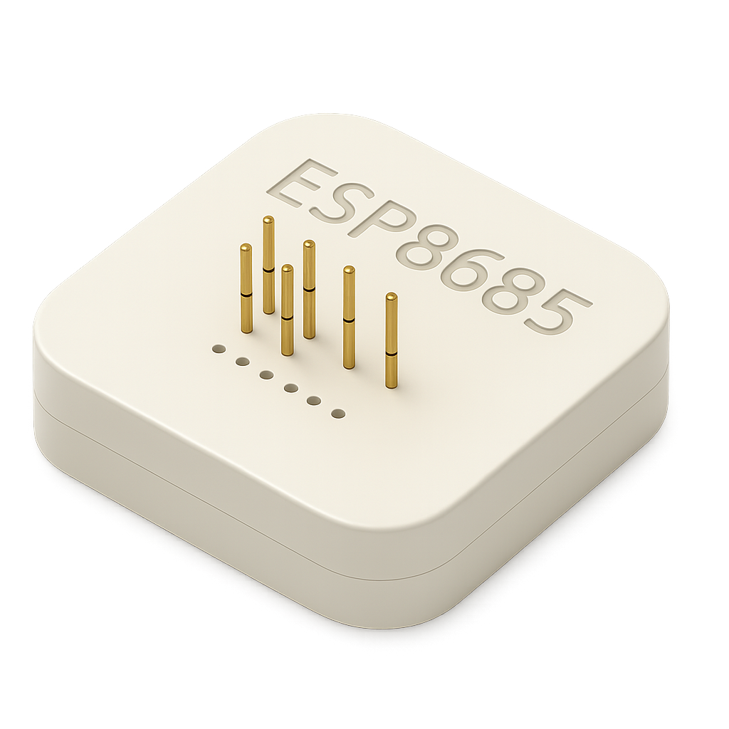
Replacing the module with an ESP8685-WROOM-03 immediately unlocks:
- Full ESP-IDF support
- Native HomeKit integration
- OTA firmware updates
- Complete GPIO control
- Long-term maintainability
Opening the Device
Tools Required
- Plastic spudgers
- Thin metal pry tool
Steps
- Insert a plastic spudger between the shell halves
- Create a small gap
- Slide in a thin metal spudger
- Slowly pry toward a corner
- Release all clips
The enclosure opens cleanly without damage.
Removing the Original Wi-Fi Module
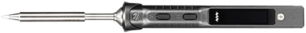
Tools Recommended
- Temperature-controlled soldering iron (TS100 / TS101 or equivalent)
- Desoldering wick
- Liquid flux
- Isopropyl alcohol
Procedure
- Take high-resolution photos of the PCB
- Apply liquid flux generously to all module pads
- Set the iron to 350–380 °C
- Remove solder using desoldering wick
- Lift the module only when all pads are free
- Clean pads and inspect carefully
Never force the module — pad damage will complicate the entire project.
Preparing the ESP8685-WROOM-03
Now that the old module is removed we can prepare the replacement module.
Magnetic Programmer
Instead of soldering headers, I built a magnetic programmer jig, you need a 3D printer. If you do not have a 3D printer you can also solder some wires to the programming pads. source: https://www.studiopieters.nl/esp8685-wroom-03 or 3D printer magnetic programmer jig Source: https://www.studiopieters.nl/esp8685-wroom-03-programmer

Benefits:
- No soldering
- Stable contact
- Works with esptool
- Fast flashing
- Low risk
Wipe Flash
esptool.py erase_flashExample output:
Chip is ESP32-D0WD-V3
Erasing flash...
Chip erase completed successfully
MAC: cc:8d:a2:dd:af:e0
⚠️ Save your MAC address — you need it when you generate the QR-Code.
Generate HomeKit QR Code
Do it yourself: https://www.studiopieters.nl/guide-to-esp32-homekit-qr-codes
Do it yourself: https://github.com/AchimPieters/esp32-homekit-qrcode
Example:
./gen_qrcode 7 693-41-208 M4T8 cc8da2ddafe0 new/qrcode.png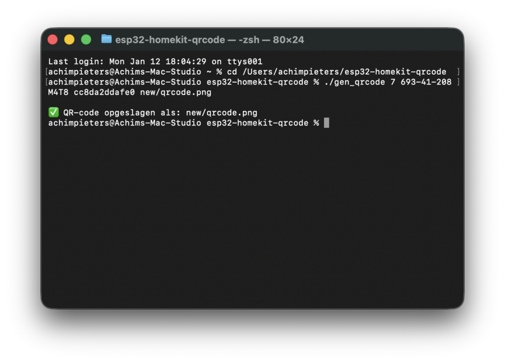
Meanings:
7= Outlet accessory693-41-208= Setup codeM4T8= Setup IDcc8da2ddafe0= MAC (no colons)
This will generate an images like this one. you can use only the QR-code if you want, or the whole image and print it as a sticker, and paste it on your plug.
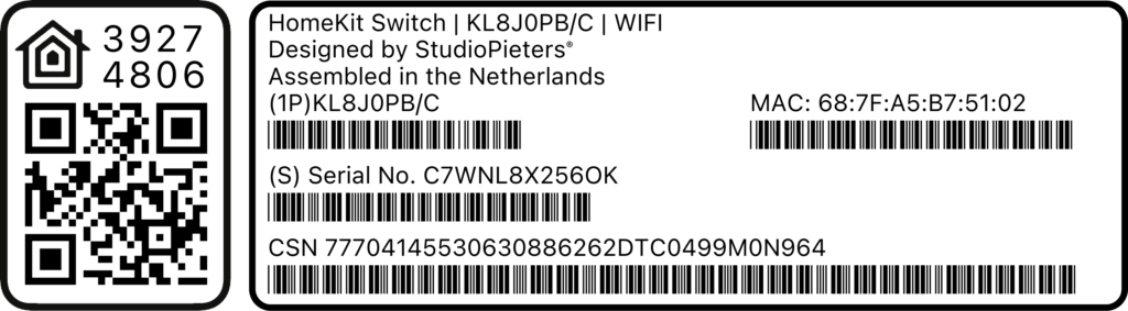
Or download precompiled qr-code here
Install Life Cycle Manager (LCM)
LCM (Life Cycle Manager) allows OTA (Over The Air) installations and updates without needing to reopening the device ever again!
Do it yourself:https://github.com/AchimPieters/esp32-lifecycle-manager
Or download precompiled files here
Go to the folder where you have placed the files and Flash:
python -m esptool --chip esp32c3 -b 460800 \
--before default_reset --after hard_reset write_flash \
--flash_mode dio --flash_size 4MB --flash_freq 80m \
0x0 build/bootloader/bootloader.bin \
0x8000 build/partition_table/partition-table.bin \
0xe000 build/ota_data_initial.bin \
0x20000 build/esp32-lifecycle-manager.bin
Installing ESP32 Lifecycle Manager (LCM)
Before installing the application firmware, install ESP32 Lifecycle Manager (LCM).
LCM is a pre-boot firmware layer that provides:
- Wi-Fi captive portal
- OTA firmware installation
- Safe update handling
- Recovery after failed updates
Repository: https://github.com/AchimPieters/esp32-lifecycle-manager
Once LCM is installed, the device never needs to be opened again.
Boot Flow Architecture
- Power is applied
- Bootloader starts
- LCM executes first
- Firmware integrity is checked
- Application starts — or LCM recovery mode is entered
This design prevents permanent soft-bricking.
Installing the ESP8685-WROOM-03
Soldering Steps
- Align the module carefully on the footprint
- Tack one corner pad
- Verify alignment on all sides
- Solder the opposite corner
- Drag-solder remaining pads using flux
- Remove solder bridges with wick
- Clean and inspect thoroughly
Take your time — visual inspection prevents most failures.
GPIO Mapping (Code-Accurate)
This firmware is Kconfig-driven. GPIO’s are not hardcoded; instead, the project provides sane defaults per target, which can be overridden in idf.py menuconfig.
Default GPIO’s for ESP8685-WROOM-03 (ESP32-C3 target)
| Function | Kconfig option | Default GPIO | Description |
|---|---|---|---|
| Wall switch input | ESP_SWITCH_GPIO | GPIO5 | External wall switch / toggle input |
| Relay control | ESP_RELAY_GPIO | GPIO4 | Drives the relay transistor/driver |
| Rear button input | ESP_BUTTON_GPIO | GPIO1 | AUBESS button input (active-low) |
| Blue status LED | ESP_BLUE_LED_GPIO | GPIO6 | Blue status LED |

To verify or change these values:
idf.py menuconfigThis makes the firmware portable across different PCB revisions.
Power Monitoring with BL0942 (UART)
The Aubess Power Monitor Switch uses a BL0942 energy-measurement IC connected via UART packet mode.
Instead of CF/CF1 pulse counting, the BL0942 periodically transmits structured serial frames containing:
- Voltage (V)
- Current (A)
- Active power (W)
- Accumulated energy (kWh)
BL0942 UART Wiring
- BL0942 RX (SDI) ← ESP UART TX
- BL0942 TX (SDO) → ESP UART RX
- SEL tied to GND (UART mode)
- Baud rate selected via hardware strap
UART-based measurement provides better robustness, simpler firmware, and easier calibration.
Wall Switch and HomeKit Synchronization
The wall switch is treated as a toggle input, not a fixed state.
Example Scenario
- Wall switch toggled → relay ON → HomeKit updates
- HomeKit turns OFF → relay off
- Wall switch toggled again → relay ON → HomeKit updates
No desynchronization is possible, regardless of control source.

Button Functions and Recovery
| Press duration | Action |
|---|---|
| < 1 second | Toggle relay |
| 30 seconds | Force LCM recovery |
Holding the button for 30 seconds always returns the device to LCM, even after a failed update.
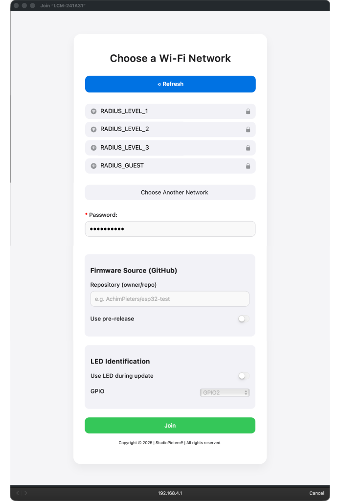
Installing Firmware via LCM
- Connect to WiFi:
LCM-XXXXX - Portal opens automatically
- Enter home WiFi credentials
- Firmware source:
AchimPieters/ESP32-power-monitor-switch - Enable GPIO6 (blue LED in this case) and Led Level On
- Click Join
The firmware installs OTA and reboots automatically.
Pairing with Apple Home
- Open the Apple Home app
- Scan the HomeKit QR code
- Assign a name and room
- Done
No cloud, no account, no vendor app.
Updating Firmware
Firmware updates are performed via HomeKit. Use the Eve app to trigger firmware updates, as Apple’s Home app does not expose update controls. Updates are OTA and safe.
Final Result
You now have:
- A power monitor switch you actually own
- Native HomeKit integration
- Accurate energy monitoring
- OTA firmware updates
- Full recovery capability
- No vendor cloud
- No telemetry
- Lifetime usability
This is the difference between a consumer IoT product and personal hardware.
Links & Resources
- ESP32 Lifecycle Manager
https://github.com/AchimPieters/esp32-lifecycle-manager - ESP32 Power Monitor Switch firmware
https://github.com/AchimPieters/ESP32-power-monitor-switch - ESP32 HomeKit framework
https://github.com/AchimPieters/esp32-homekit - HomeKit QR-code generator
https://github.com/AchimPieters/esp32-homekit-qrcode - More projects
https://www.studiopieters.nl