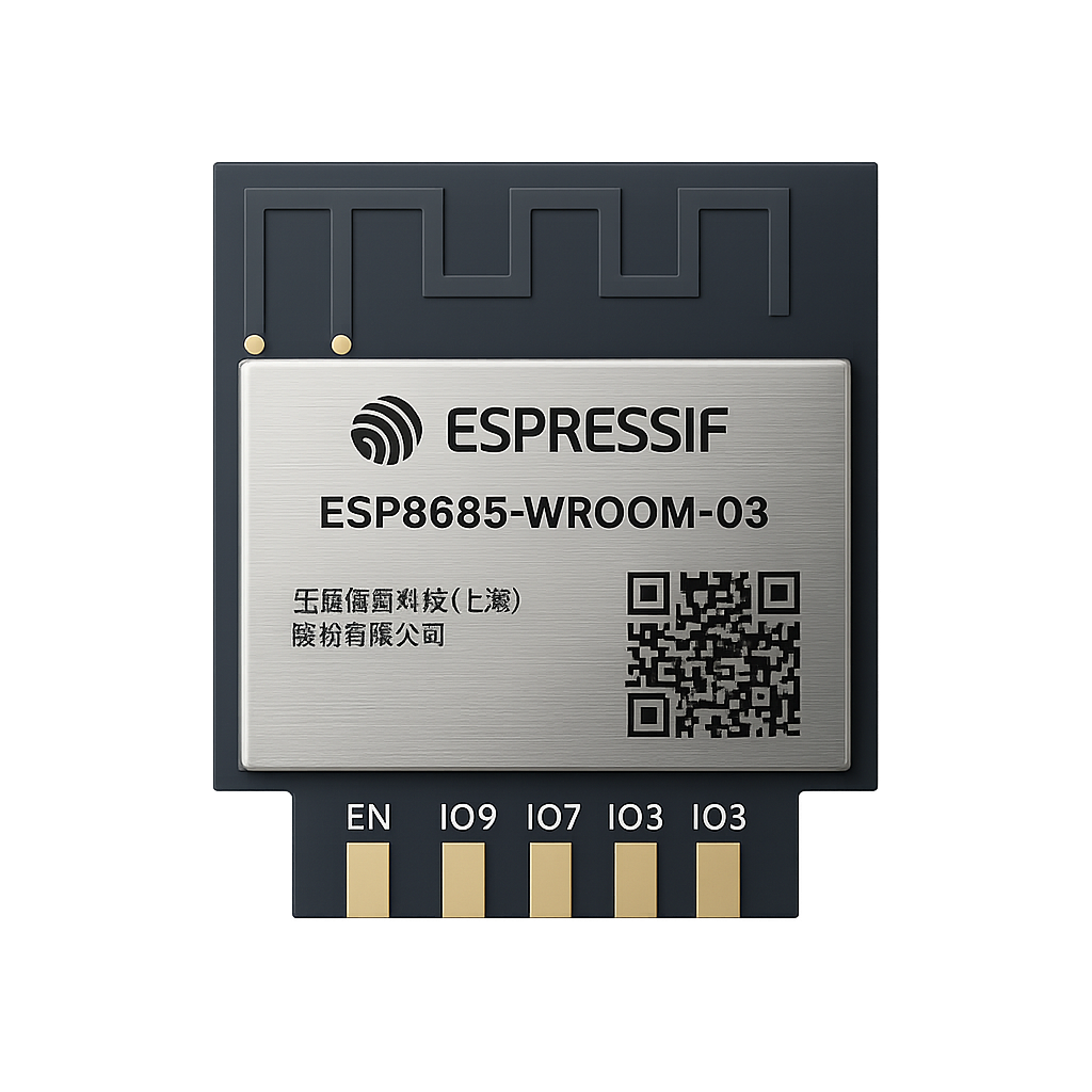
The ESP8685-WROOM-03 is one of Espressif’s most compact and efficient wireless modules, combining Wi-Fi and Bluetooth 5 LE connectivity with a RISC-V single-core processor and rich peripherals — all in a module only 15 × 17.3 mm in size. It is designed for modern IoT applications that demand reliability, low power consumption, and flexible integration. Whether you’re a maker or a professional engineer, this guide explains everything you need to know about the ESP8685-WROOM-03 pinout, peripherals, and usage.
What is the ESP8685-WROOM-03?
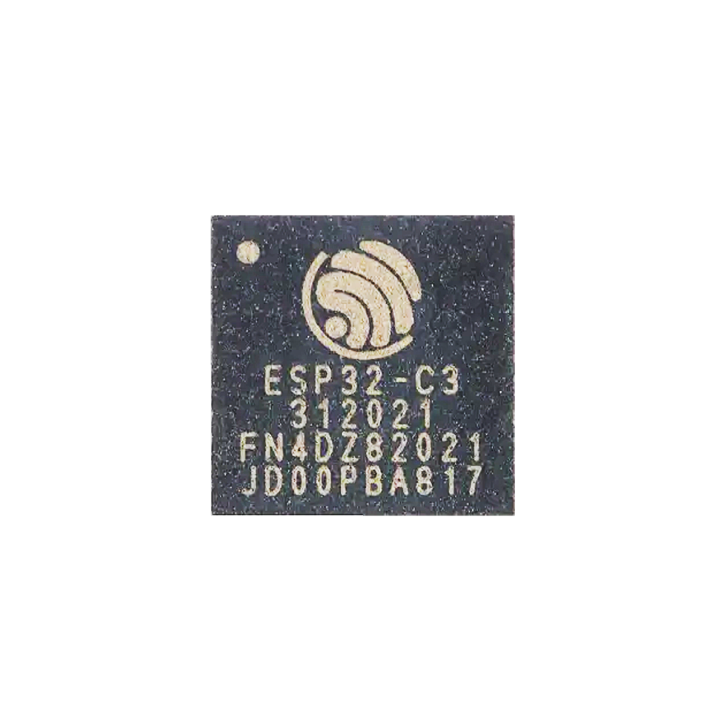
System-on-Chip (SoC)
At the heart of this module lies the ESP8685H4 SoC — a 32-bit RISC-V single-core processor running up to 160 MHz.
It integrates:
- 384 KB ROM
- 400 KB SRAM (with 16 KB for cache)
- 8 KB RTC SRAM
- 4 MB in-package SPI flash memory
Connectivity
- Wi-Fi: IEEE 802.11 b/g/n (2.4 GHz, 20 MHz / 40 MHz bandwidth)
- Bluetooth 5 LE: supports 125 Kbps, 500 Kbps, 1 Mbps, 2 Mbps, and Bluetooth Mesh
- Integrated coexistence mechanism between Wi-Fi and BLE sharing the same PCB antenna
Module Design
The ESP8685-WROOM-03 integrates:
- ESP8685H4 chip
- 40 MHz crystal oscillator
- 4 MB Quad SPI flash
- Passive components
- On-board PCB antenna
Operating voltage: 3.0 – 3.6 V
Operating temperature: –40 °C to +105 °C

Designed for Connectivity and Control
Despite its small size and single core, the ESP8685-WROOM-03 supports a comprehensive set of features:
| Feature | Specification |
|---|---|
| CPU | 32-bit RISC-V single core @ 160 MHz |
| Memory | 384 KB ROM, 400 KB SRAM, 4 MB Flash |
| Wi-Fi | 802.11 b/g/n (2.4 GHz), 1T1R up to 150 Mbps |
| Bluetooth | Bluetooth 5 LE + Mesh |
| GPIO | Up to 8 programmable GPIOs (3 strapping) |
| ADC | 12-bit SAR ADC (5 channels on ADC1, 1 on ADC2) |
| Peripherals | SPI, I²C, I²S, UART, TWAI (CAN 2.0), PWM, RMT, USB Serial/JTAG |
| Power modes | Active, Modem-sleep, Light-sleep, Deep-sleep (5 µA typ.) |
| Package size | 15 × 17.3 × 2.8 mm |
With these capabilities, the ESP8685-WROOM-03 is ideal for ESP32-HomeKit, smart homes, industrial automation, health-care wearables, and low-power IoT sensors.
ESP8685-WROOM-03 Pinout Overview
Unlike the larger ESP32 modules, the ESP8685-WROOM-03 provides 11 physical pins with 8 usable GPIO’s.
Below is the official pinout summary.
| Pin No. | Name | Type | Default / Function |
|---|---|---|---|
| 1 | EN | Input | Chip enable — High = ON, Low = power off (pulled up internally) |
| 2 | IO1 | I/O/T | GPIO1 / ADC1_CH1 / XTAL_32K_N |
| 3 | IO6 | I/O/T | GPIO6 / FSPICLK / MTCK / LED PWM |
| 4 | IO7 | I/O/T | GPIO7 / FSPID / MTDO / LED PWM |
| 5 | IO3 | I/O/T | GPIO3 / ADC1_CH3 / LED PWM |
| 6 | 3V3 | Power | 3.0 – 3.6 V supply |
| 7 | GND | Power | Ground |
| 8 | RX | I/O/T | GPIO20 / U0RXD |
| 9 | TX | I/O/T | GPIO21 / U0TXD |
| 10 | IO5 | I/O/T | GPIO5 / ADC2_CH0 / FSPIWP / MTDI / LED PWM |
| 11 | IO4 | I/O/T | GPIO4 / ADC1_CH4 / FSPIHD / MTMS / LED PWM |
Note: IO2, IO8, and IO9 are internal strapping pins and not exposed on the module edge.
Boot Configuration
The ESP8685 uses three strapping pins (GPIO2, GPIO8, GPIO9) to define its boot behavior.
| Boot Mode | GPIO2 | GPIO8 | GPIO9 | Description |
|---|---|---|---|---|
| SPI Boot Mode | 1 | Any | 1 | (Default) Boot from internal SPI flash |
| Joint Download Mode | 1 | 1 | 0 | Used for flashing via USB Serial/JTAG or UART |
To flash firmware manually:
- Hold GPIO9 LOW
- Reset or power-cycle the module
- Use UART0 or USB Serial/JTAG to upload firmware
Peripheral Functions
UART
- Two UART controllers (UART0 & UART1)
- UART0 (GPIO20 = RX, GPIO21 = TX) used for programming and serial logs
- Up to 5 Mbps, hardware and software flow control
SPI
- SPI0 and SPI1 used for in-package flash
- SPI2 available for user peripherals (up to 80 MHz clock)
I²C
- Supports master and slave modes
- 100 kHz, 400 kHz, and 800 kHz operation
I²S
- Full-duplex audio interface, 8- to 32-bit data widths
- Supports PCM and PDM formats
TWAI® (CAN 2.0)
- Fully compliant with ISO 11898-1 standard
- 1 Mbps maximum bit rate
LED PWM Controller
- Up to 6 independent channels
- 14-bit duty cycle resolution
- Supports smooth fade transitions (e.g., breathing effects)
RMT (Remote Control Peripheral)
- 2 TX + 2 RX channels for infrared or single-wire protocols
ADC
- 12-bit SAR ADC
- ADC1: 5 channels (GPIO1, GPIO3, GPIO4, GPIO5, GPIO6)
- ADC2: 1 channel (GPIO5)
Use ADC1 for reliable readings during Wi-Fi operation.
Temperature Sensor
- Measures chip temperature (–40 °C to 125 °C) for calibration and diagnostics
Electrical and Power Characteristics
| Parameter | Typical Value | Notes |
|---|---|---|
| Supply Voltage | 3.3 V | 3.0 – 3.6 V range |
| Active TX Current (802.11b @ 20 dBm) | ~ 340 mA | Peak TX load |
| RX Current | ~ 84 mA | Idle CPU |
| Modem-Sleep Current | 13 – 23 mA | Depends on CPU state |
| Light-Sleep Current | ≈ 130 µA | Wi-Fi off |
| Deep-Sleep Current | ≈ 5 µA | RTC only |
| Power-Off Current | ≈ 1 µA | EN = LOW |
Programming the ESP8685-WROOM-03
Supported Environments
- Arduino IDE (ESP32-C3 board support)
- PlatformIO (esp32c3 platform)
- Espressif ESP-IDF v5 or later
Programming Pins
| Function | Pin | Description |
|---|---|---|
| TXD0 | GPIO21 | ESP8685 → Mac (serial output) |
| RXD0 | GPIO20 | Mac → ESP8685 (serial input) |
| EN | EN | Reset / enable input |
| GPIO9 | — | Boot mode strap (low = flash mode) |
Flashing Steps

- Connect TX, RX, 3V3, and GND to your USB-to-serial adapter.
- Pull GPIO9 LOW (RTS) and reset the module.
- Flash via
esptool.pyor ESP-IDF GUI. - Release GPIO9 (DTR) and reset again to run your program.
Newer development boards often automate boot mode control via USB Serial/JTAG.
Best Practices and Common Mistakes
Do this
- Use RC delay (10 kΩ + 1 µF) on EN for stable startup.
- Keep antenna area free of copper and metal.
- Use ADC1 channels for analog sensing during Wi-Fi operation.
- Provide sufficient power headroom (≥ 500 mA).
- Respect strapping pin levels at boot (GPIO9 in particular).
Avoid
- Pulling down EN unexpectedly.
- Driving strapping pins high or low during boot unless intended.
- Re-purposing UART0 pins while flashing firmware.
Conclusion: Compact Power for the Next Generation of IoT
The ESP8685-WROOM-03 distills Espressif’s wireless expertise into a miniature, cost-efficient, and robust platform.
With its RISC-V core, Wi-Fi + Bluetooth 5 LE, USB Serial/JTAG, and 8 GPIO’s, it brings next-generation IoT capabilities to even the smallest devices — from smart sensors to wearables. Mastering the ESP8685 pinout opens the door to powerful and energy-efficient designs ready for the future.