
HomeKit
ESP8266 HomeKit Thermostat with OLED Display
A HomeKit thermostat on an ESP8266 that heats and cools, with a DHT22 sensor, a small OLED display and UP and DOWN buttons that change the set temperature by 0.5 degrees.
- ESP8266
- HomeKit
- 3 min read
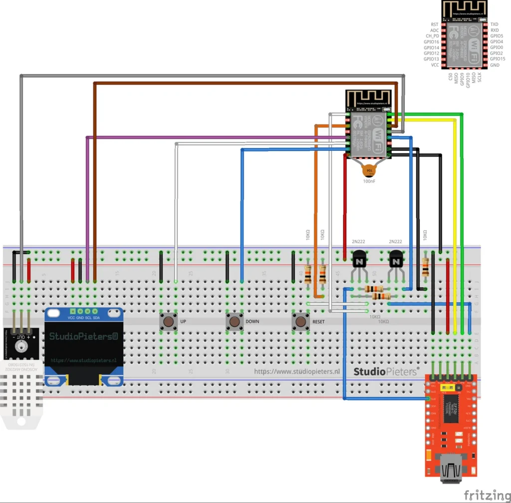
A HomeKit thermostat built on an ESP8266. It measures the temperature with a DHT22 sensor, has a small OLED display, and lets you change the set temperature with two buttons, next to the Home app. It can both heat and cool, as the HomeKit Accessory Protocol thermostat service allows.
It is a test setup, and a fun one, that combines the thermostat with an OLED display. It was built to see whether the code and the hardware work together.
What it does
| Feature | Details |
|---|---|
| HomeKit thermostat | Appears in the Home app as a thermostat that can heat and cool |
| Temperature sensor | A DHT22 (AM2302) |
| Display | A small I²C OLED display |
| UP and DOWN buttons | Change the set temperature in steps of 0.5 °C |
| Updates | Over the air, through Life Cycle Manager 2 |
| No cloud | Control stays on your own network |
Hardware
| Component | Notes |
|---|---|
| ESP8266 module | An Ai-Thinker ESP8266 module of the ESP-12 type. See the ESP8266 pinout |
| AM2302 (DHT22) sensor | Temperature and humidity, on a breakout with the pins marked minus, OUT and plus |
| OLED display | I²C, with VCC, GND, SCL and SDA pins. See the SSD1306 OLED display guide |
| 3 push buttons | UP, DOWN and RESET |
| 2 NPN transistors | Drawn as 2N222 in the diagram, with 10 kΩ resistors, for the automatic programming circuit |
| 100 nF capacitor | Between the supply and ground at the module |
| USB-serial (FTDI) adapter | For flashing and for power in this test setup. Set it to 3.3 V logic |
Wiring
The Fritzing diagram at the top of this page shows the whole build on a breadboard, and includes the pinout of the module. Reading the wires against that pinout gives this assignment:
| Part | ESP8266 pin |
|---|---|
| DHT22 (AM2302) data, OUT | GPIO4 |
| OLED SDA | GPIO5 |
| OLED SCL | GPIO14 |
| UP button | GPIO12 |
| DOWN button | GPIO13 |
| RESET button | RST |
| Enable line | CH_PD, pulled up with a 10 kΩ resistor |
| Boot mode | GPIO15 to GND |
| Serial to the FTDI adapter | TXD and RXD |
These pins are read from the diagram and are not listed in the repository text, so check them against the diagram before you build. Use an FTDI adapter set to 3.3 V, because a 5 V adapter can damage the module.
Automatic programming circuit
The two transistors and their 10 kΩ resistors form an automatic programming circuit. It drives the programming GPIOs of the module for you, so you do not have to press buttons to put the module in flash mode.
Flash and install
The installation is the same as for the other ESP8266 HomeKit accessories on this site. The firmware runs on ESP-Open-RTOS with Life Cycle Manager 2, which sets up the WiFi and installs updates over the air. The full steps, from installing esptool to flashing, joining the LCM- WiFi network and pairing, are in ESP8266 HomeKit Blinds.
In the portal, use these values:
| Field | Value |
|---|---|
| OTA repository | AchimPieters/ESP8266-HomeKit-Thermostat |
| OTA binary file | main.bin |
When the installation is done, scan the QR code the device generates in the Home app to add it.
Firmware release
| Version | Date | Notes |
|---|---|---|
| 0.0.1 | 3 November 2019 | Initial release |
The firmware is published as a binary, main.bin, with a signature file, main.bin.sig.
Good to know
- This is a test setup and not a finished product.
- The HomeKit Accessory Protocol specification the firmware follows is the non-commercial version, for accessories you build yourself and do not distribute or sell.
- The repository has the diagram and the MIT licence, but no source code.
Everything is in the ESP8266-HomeKit-Thermostat repository on GitHub.
Related
 HomeKit
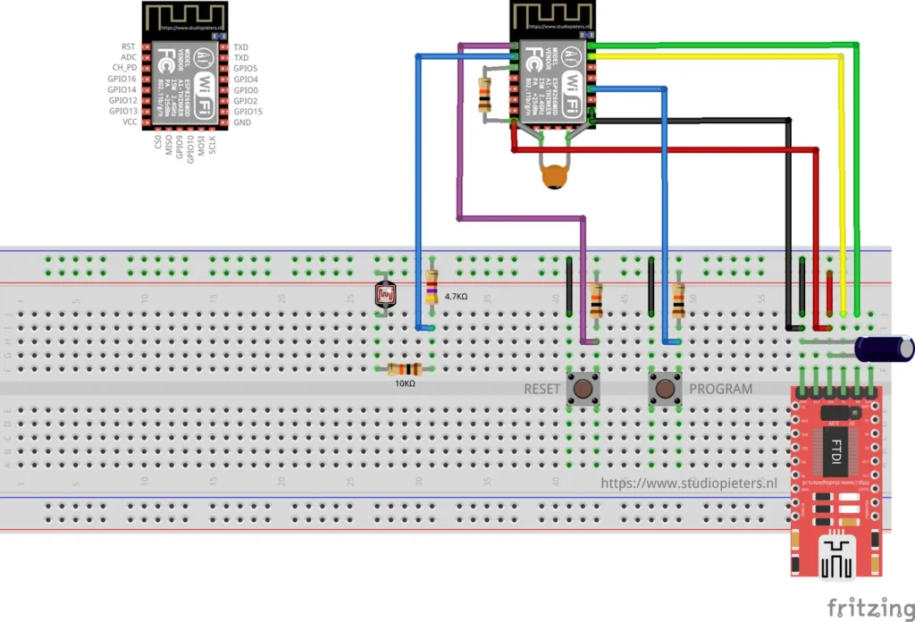
ESP8266 HomeKit Light Sensor Test with an LDR
A very simple test of an LDR on the analog input of an ESP8266 as a HomeKit light sensor, and why it does not give useful measurements.
Read more
HomeKit
ESP8266 HomeKit Light Sensor Test with an LDR
A very simple test of an LDR on the analog input of an ESP8266 as a HomeKit light sensor, and why it does not give useful measurements.
Read more
 HomeKit
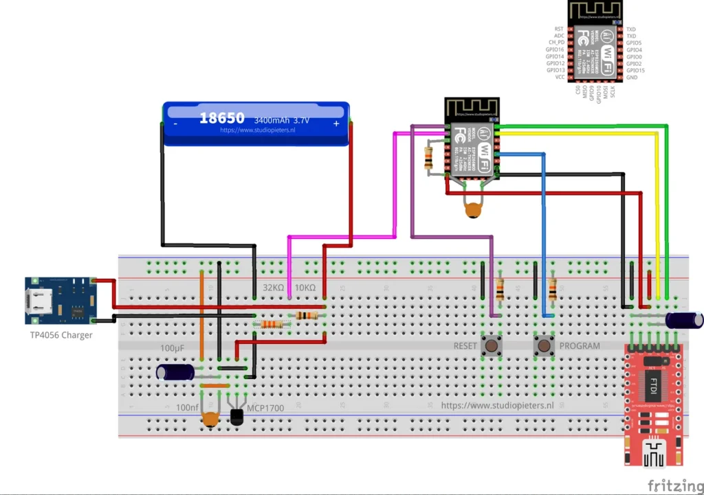
ESP8266 HomeKit Battery Status with an 18650 Cell
A proof of concept: an ESP8266 that measures an 18650 cell through a voltage divider and reports a low battery to Apple Home.
Read more
HomeKit
ESP8266 HomeKit Blinds Contact Sensor
A contact sensor for blinds in Apple HomeKit: the Home app shows whether the blinds are open or closed.
Read more
HomeKit
ESP8266 HomeKit Battery Status with an 18650 Cell
A proof of concept: an ESP8266 that measures an 18650 cell through a voltage divider and reports a low battery to Apple Home.
Read more
HomeKit
ESP8266 HomeKit Blinds Contact Sensor
A contact sensor for blinds in Apple HomeKit: the Home app shows whether the blinds are open or closed.
Read more
More HomeKit
Keep building.
Switches, sensors, plugs and blinds: more accessories that you build yourself and add to the Home app.
All HomeKit