Recently I walked through the Action and saw an assortment of smart home products here. My attention was drawn to the wifi logo on the box. I decided to take a Power Plug with me to investigate it further.
Power plug
The power plug is from the brand LSC which is again part of Tuya, a Chinese company. To operate the smart plug you need to download an app, with which you can operate the power plug. It is also possible to operate the Power Plug trough voice control of Google Assistant and Amazon Alexa.
Privacy
Because you need an app to operate this smart Power Plug, I am immediately critical, also the control with my voice trough Google Assistant and Amazon Alexa do not have my preference. All these options are known for hoarding your data. That’s why I’m going to see if I can install my own firmware based on HomeKit. Without hidden software and collecting my data.

teardown
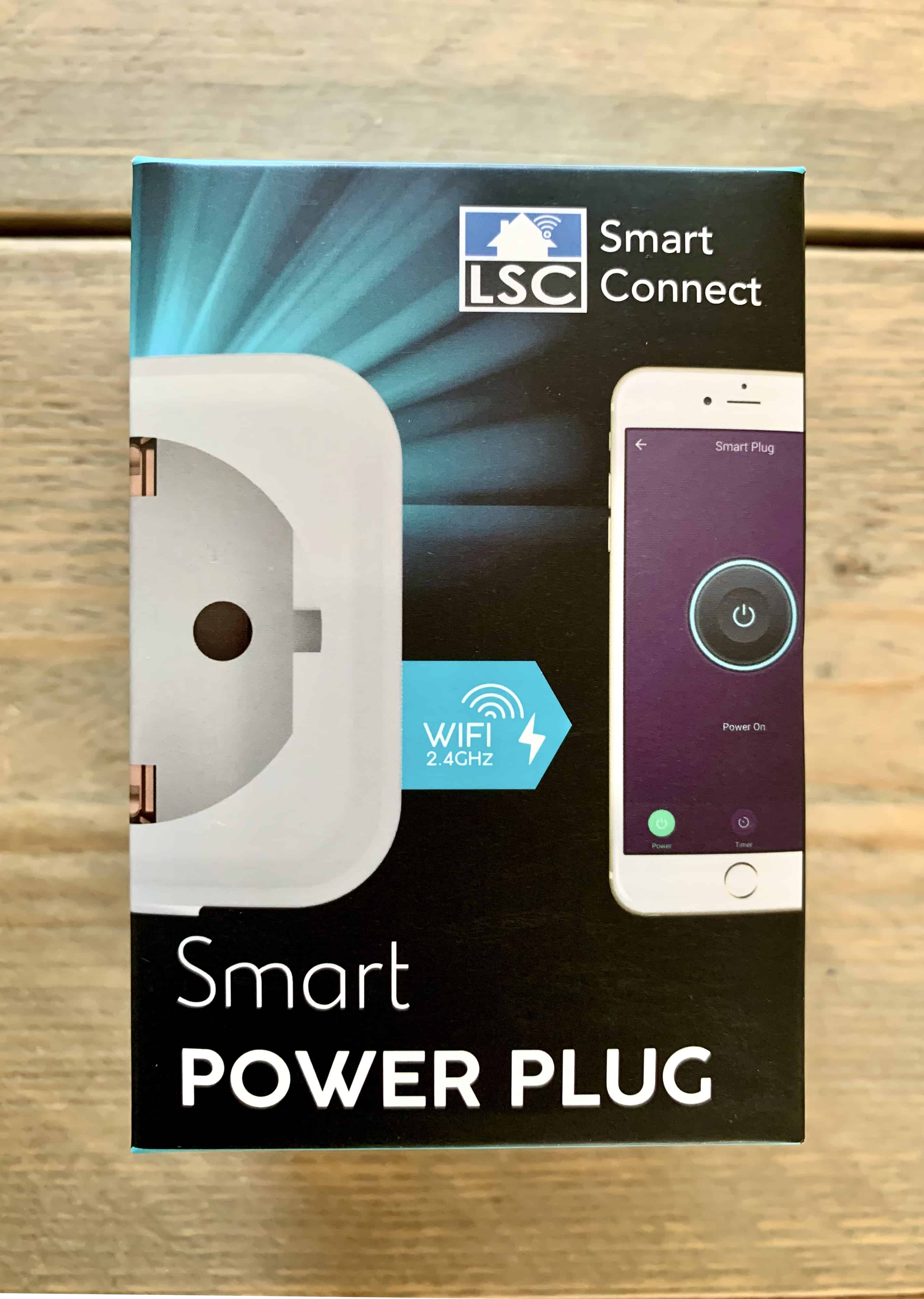
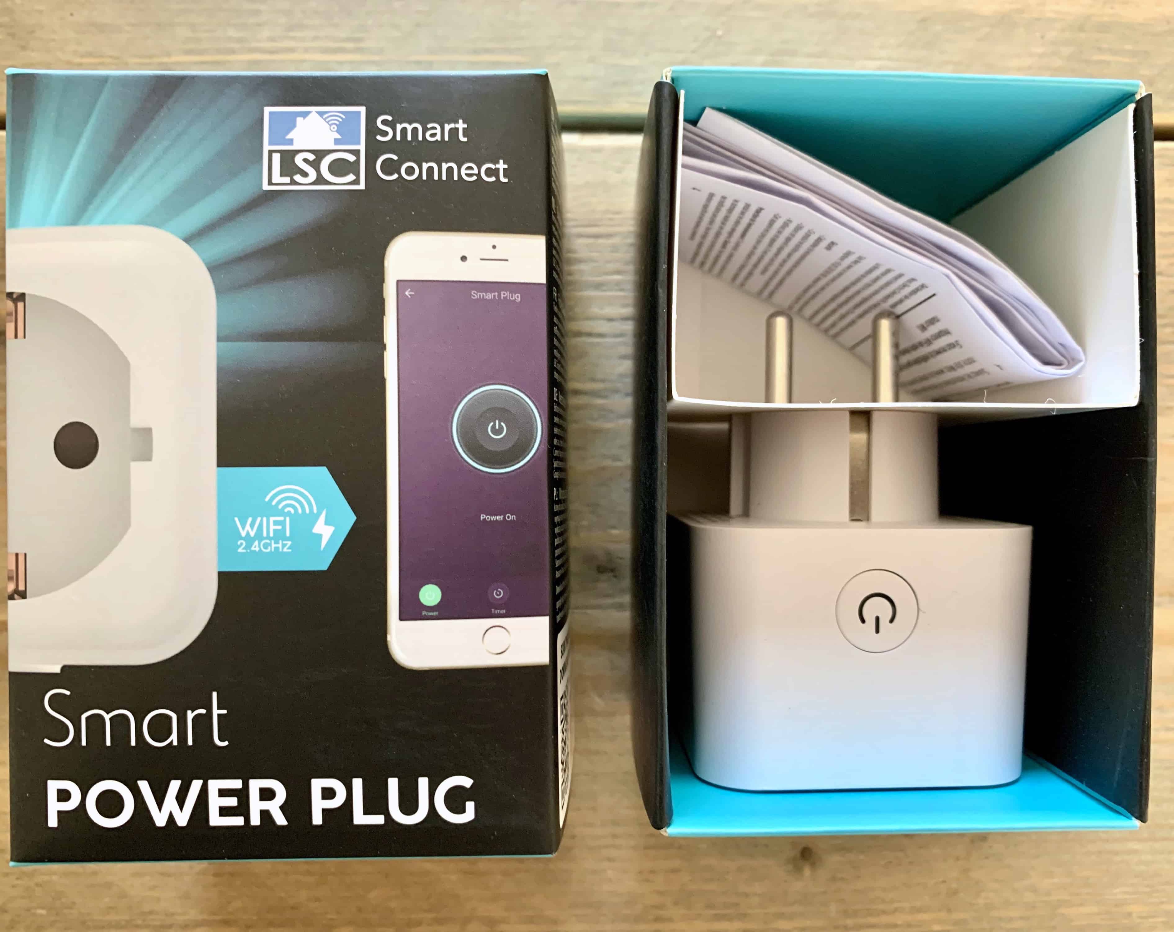
For a good reference I start with the packaging of the Power Plug, as you can see a nice clean packaging. Inside the packaging we find the Power Plug and a small multi language manual.
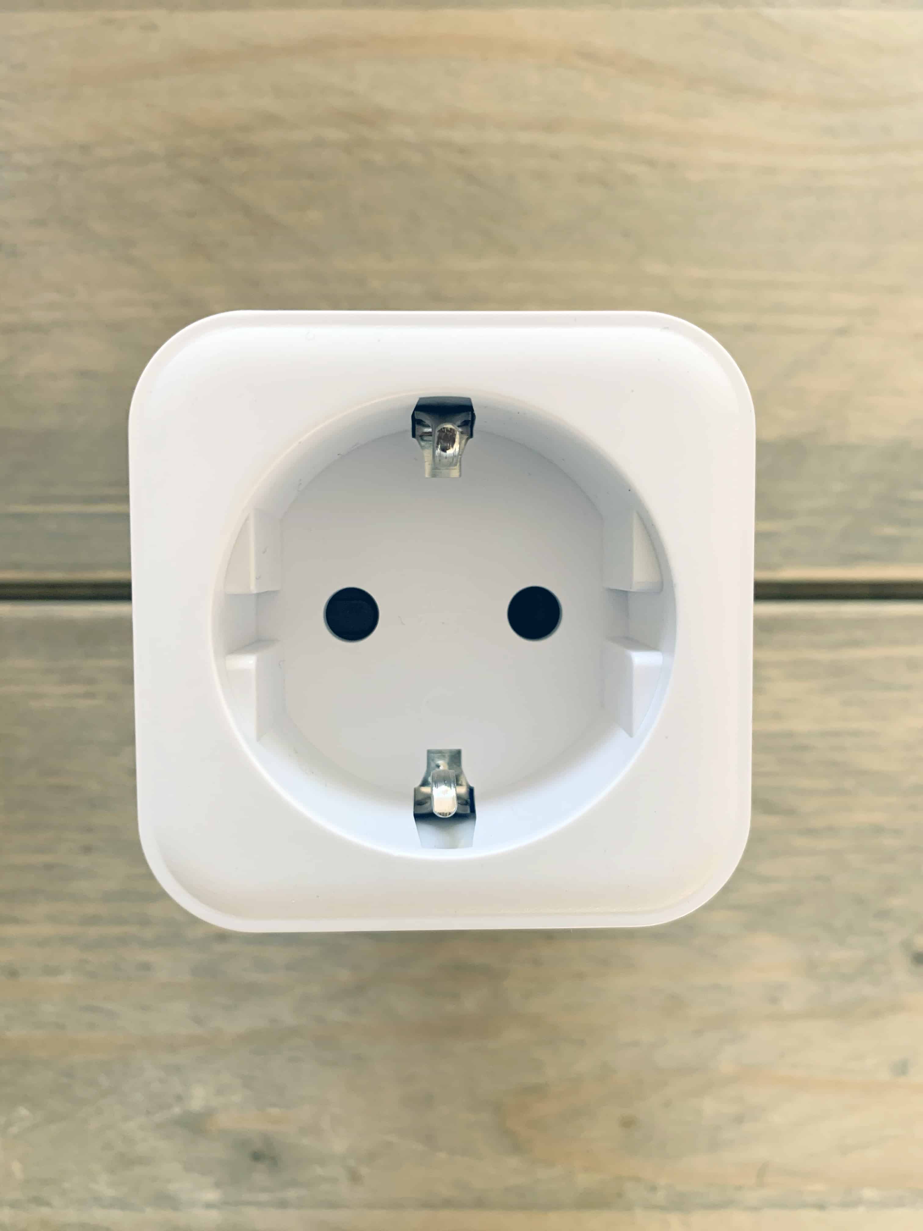
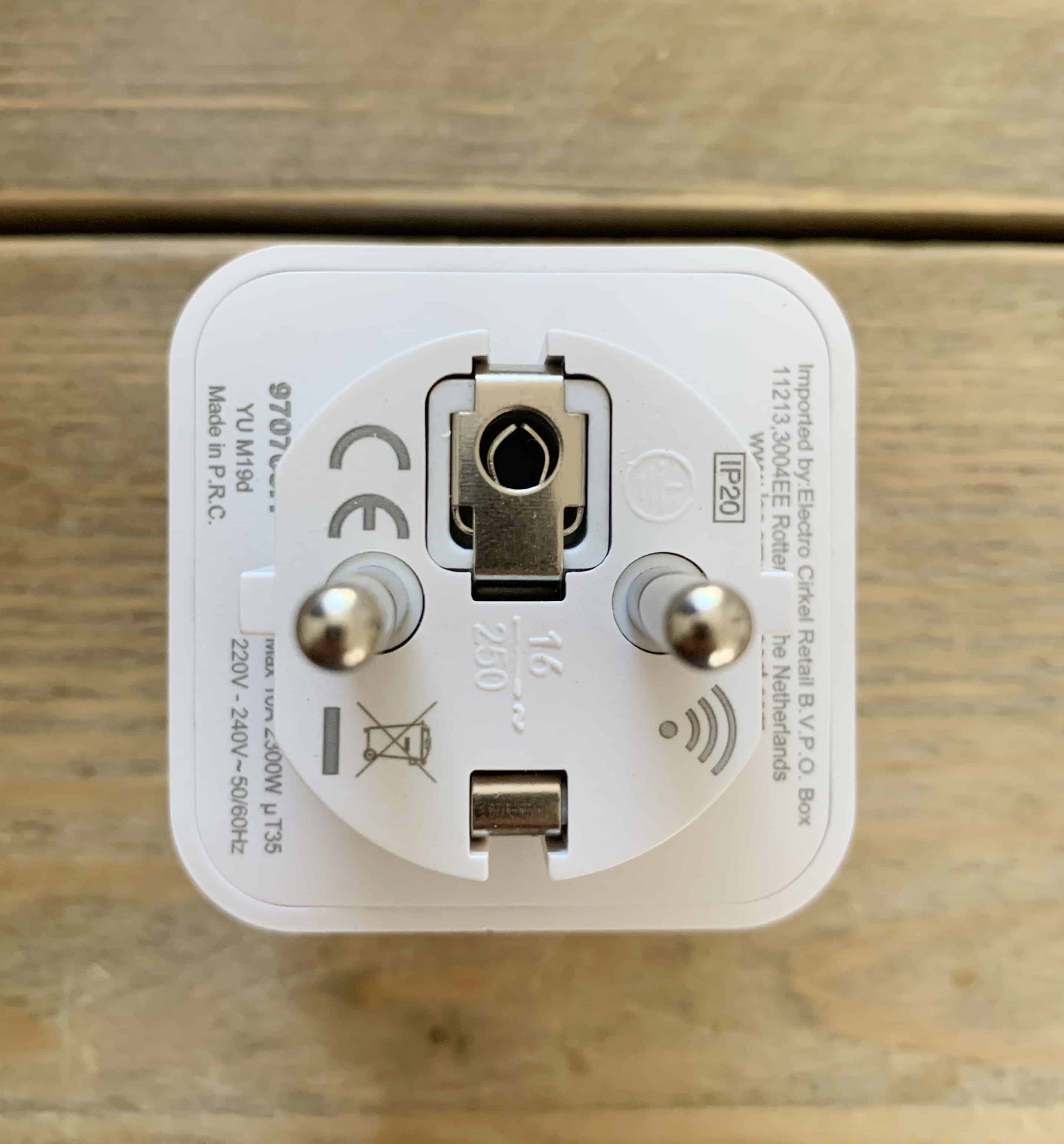
The PowerPlug has a nice clean finish, and only at the back of the plug we find some information.
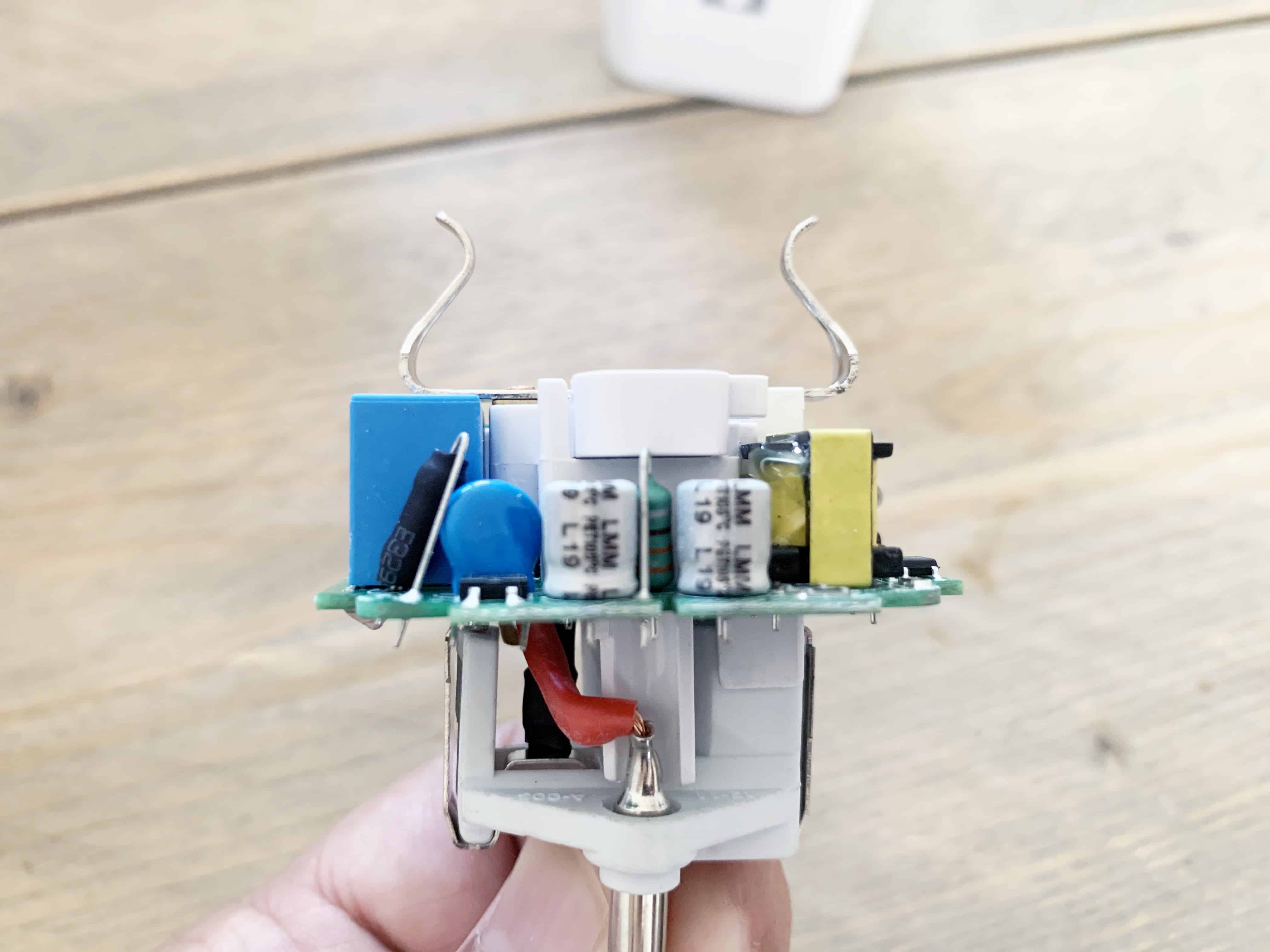
Here’s the tricky part, getting opening the enclosure without damaging it. As you can see the housing isn’t made in a cheap way and is firmly connected together. Once opened all parts easy come apart.
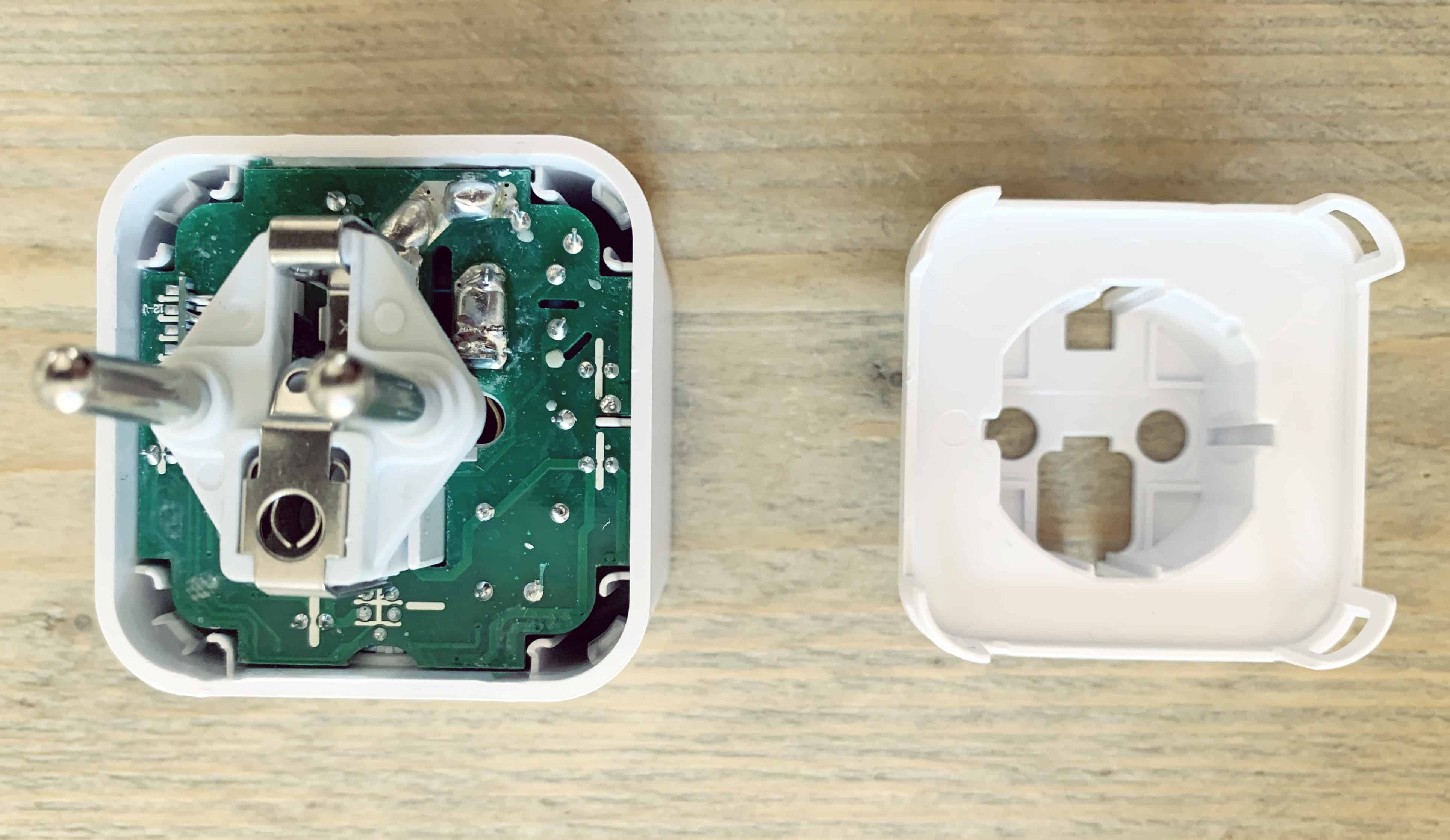
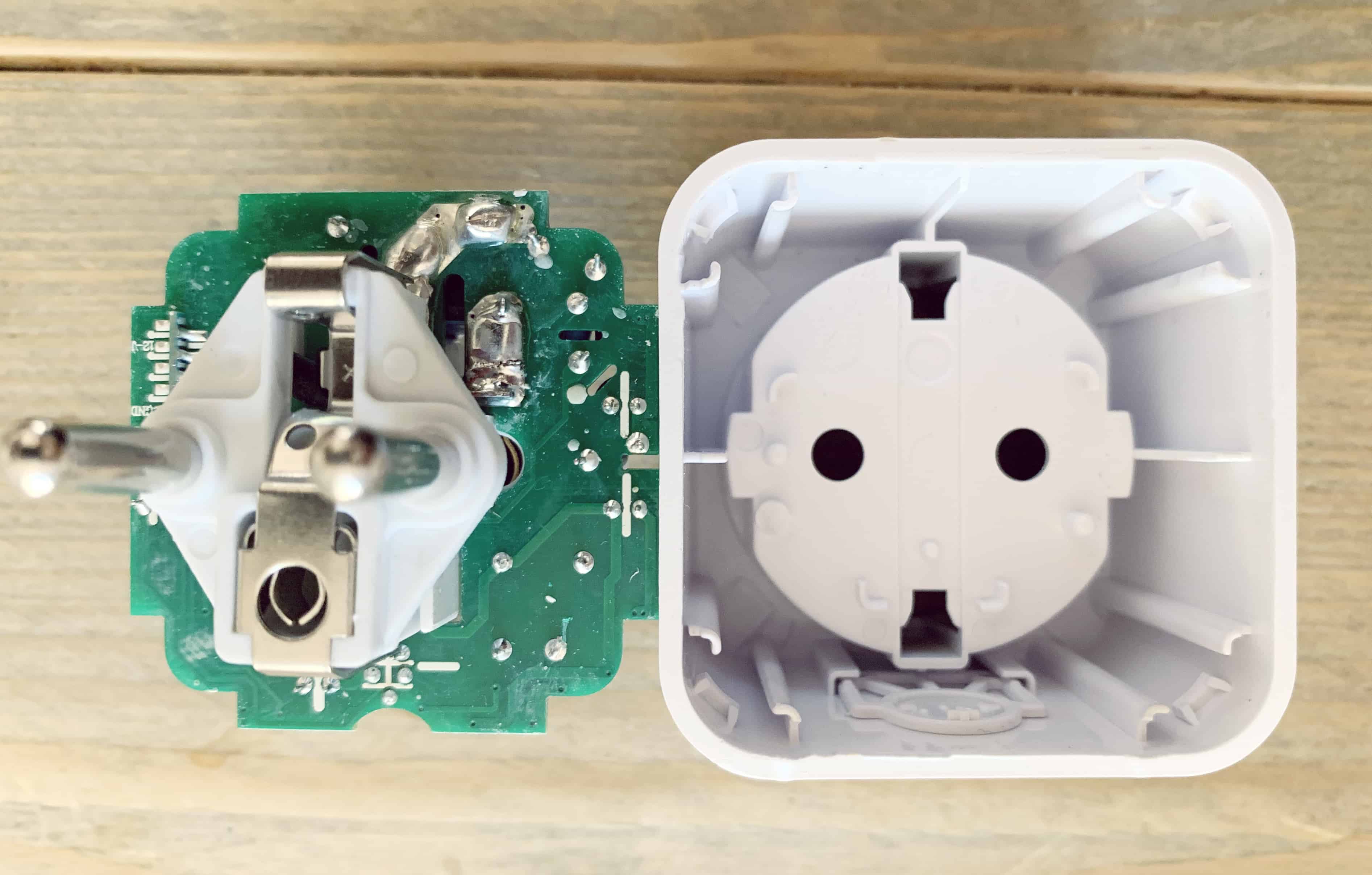
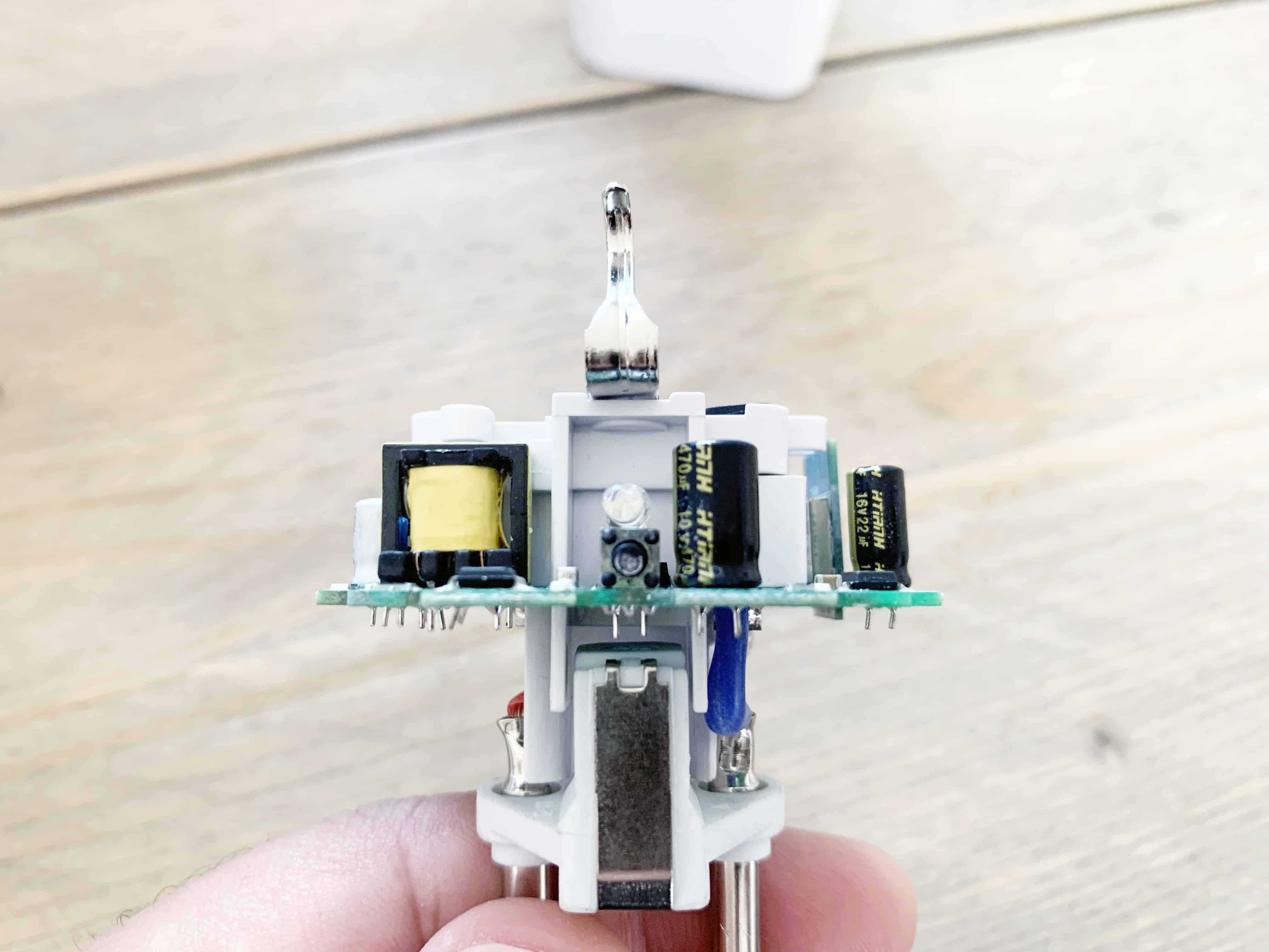
As we inspecting the PCB we cab see that the Power plug is made only with a few components.
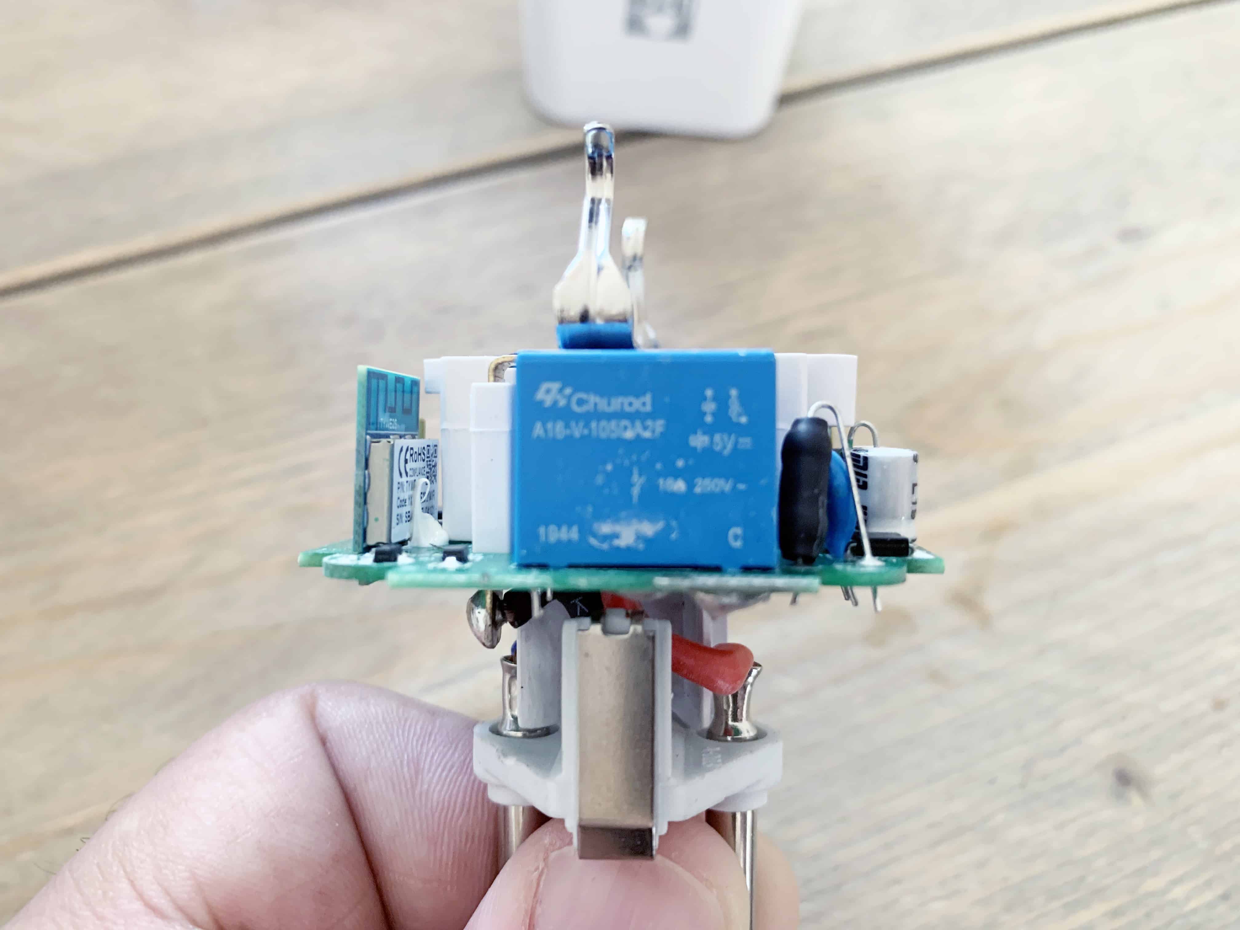
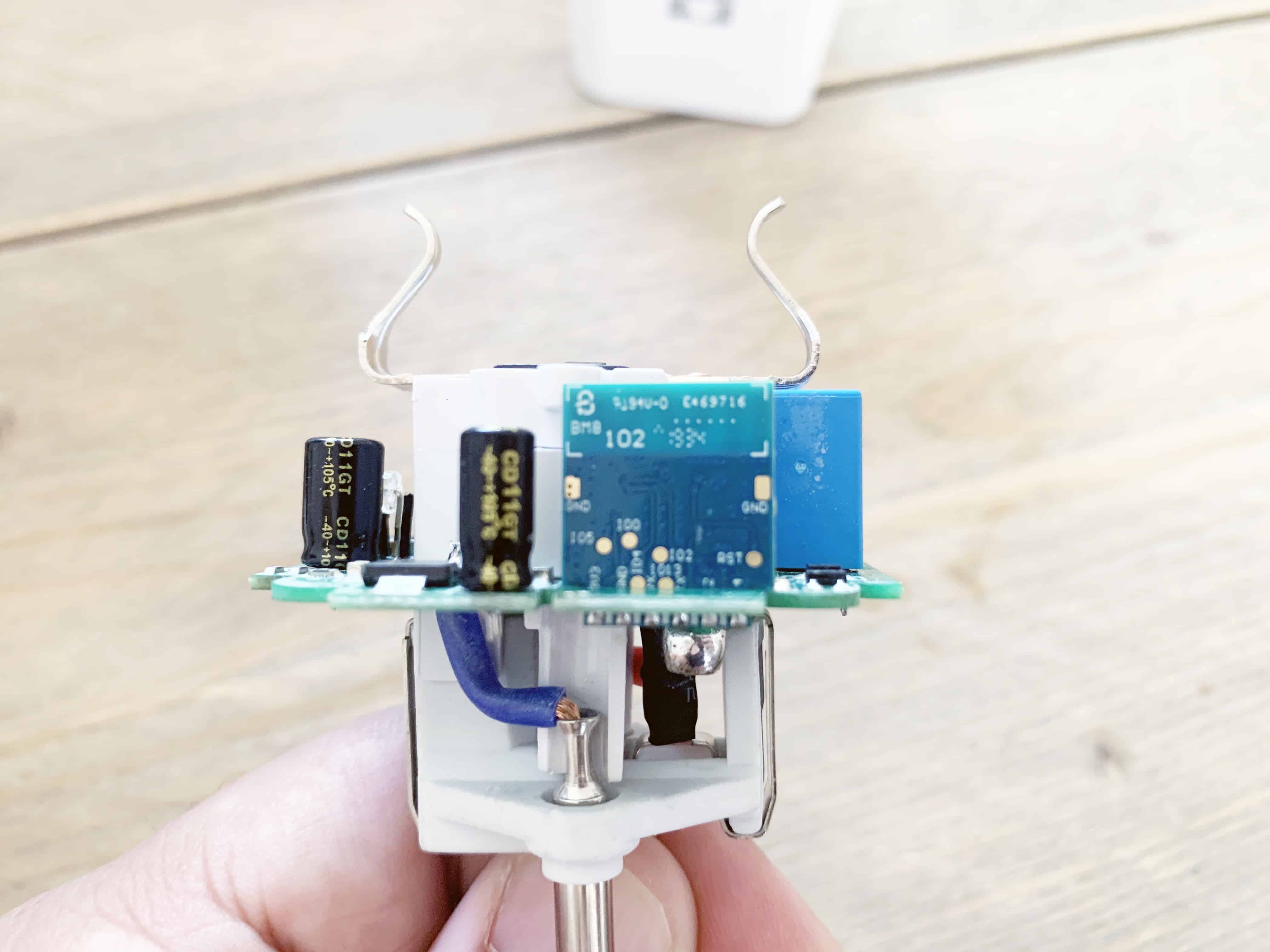
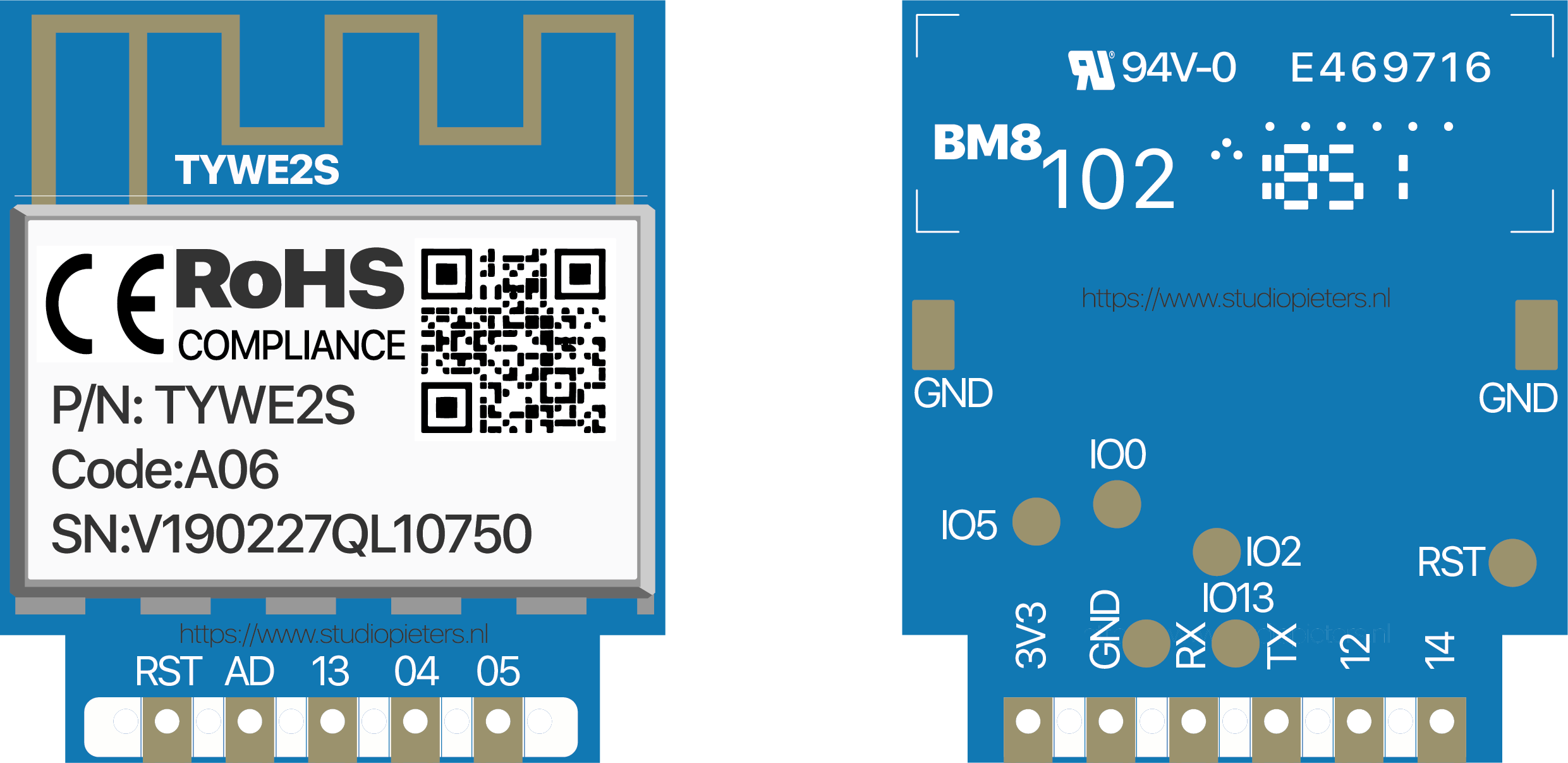
On the main PCB we find the WIFI Module I can read its model name, TYWE2S. And this seems to be an ESP8285, which is hackable!
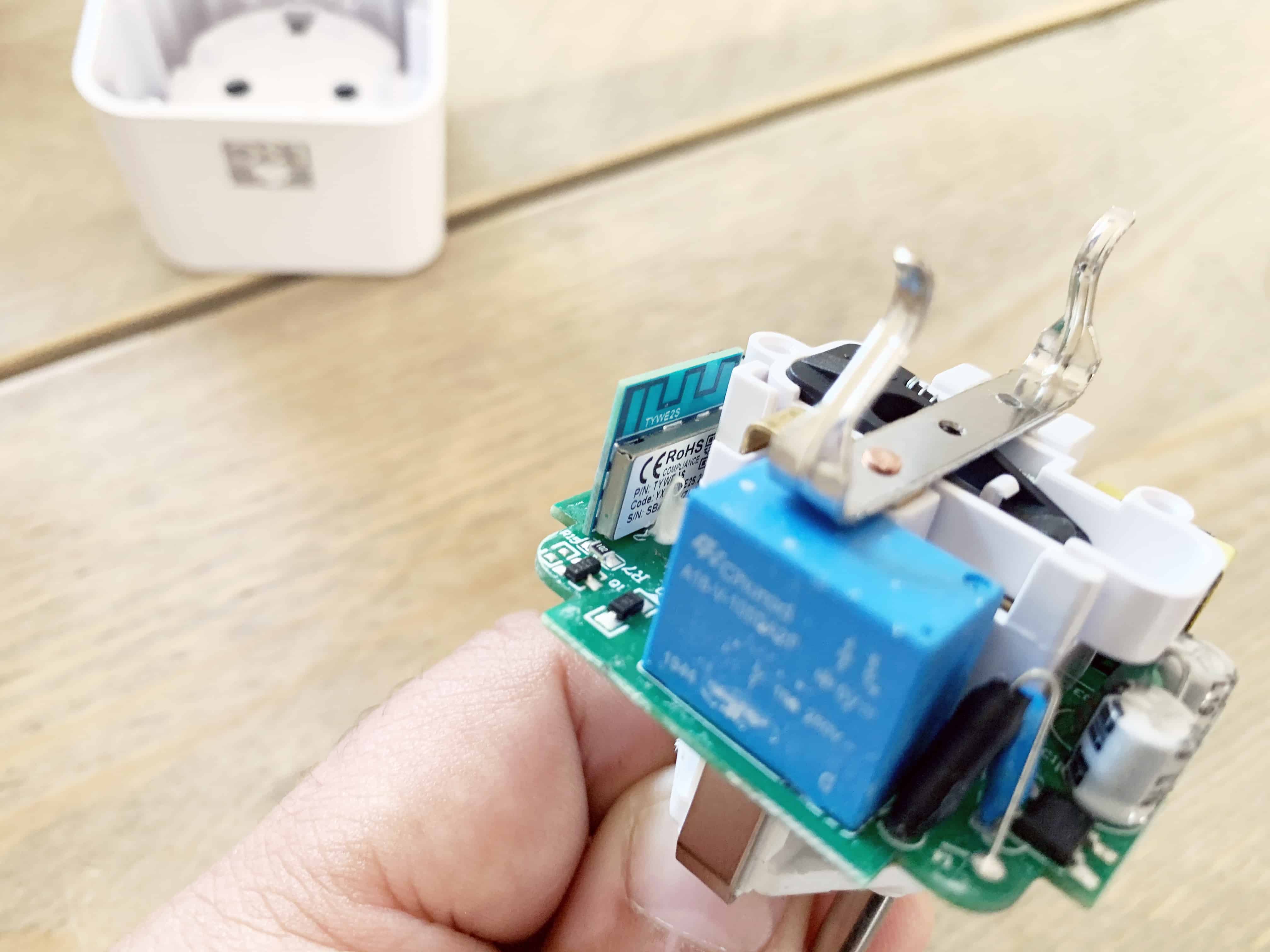

After some searching the internet I found out how to Flash this module, the only thing it isn’t done with a ESP-HomeKit firmware.
Hardware
Fore referent I draw the module so you can see how it looks and how to connect is. The module has Connectors not he front and back. Also on the back is has some connecting pad’s. On the front we find Reset an Analog/digital GPIO, GPIO13, GPIO4 and GPIO5. On the back You see the Power pad 3.3V, Ground, RX, TX, GPIO12 and GPIO14. We also see some Testing pads two times Ground, GPIO0, GPIO5, GPIO4, GPIO2, GPIO13 and Reset.
So how to connect the module to a FTDI USB to TTL Serial Adapter Module. At first make sure your FDTI Module has it jumper set to 3.3V. Then Connect the wires as you can see in this scheme.
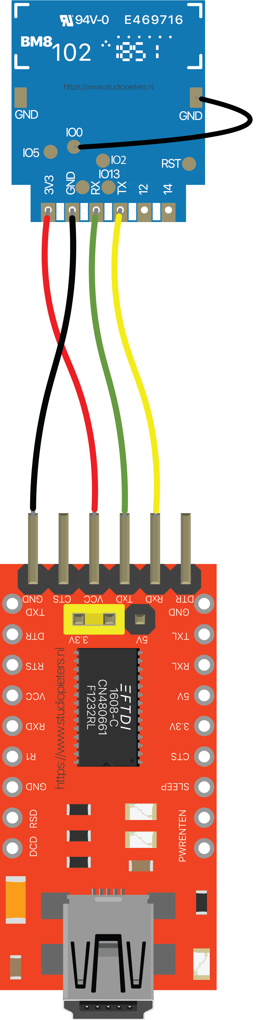
| TYWE2S Module | FDTI Module |
| 3.3V | VCC |
| GND | GND |
| RX | TX |
| TX | RX |
| IO0 | GND |
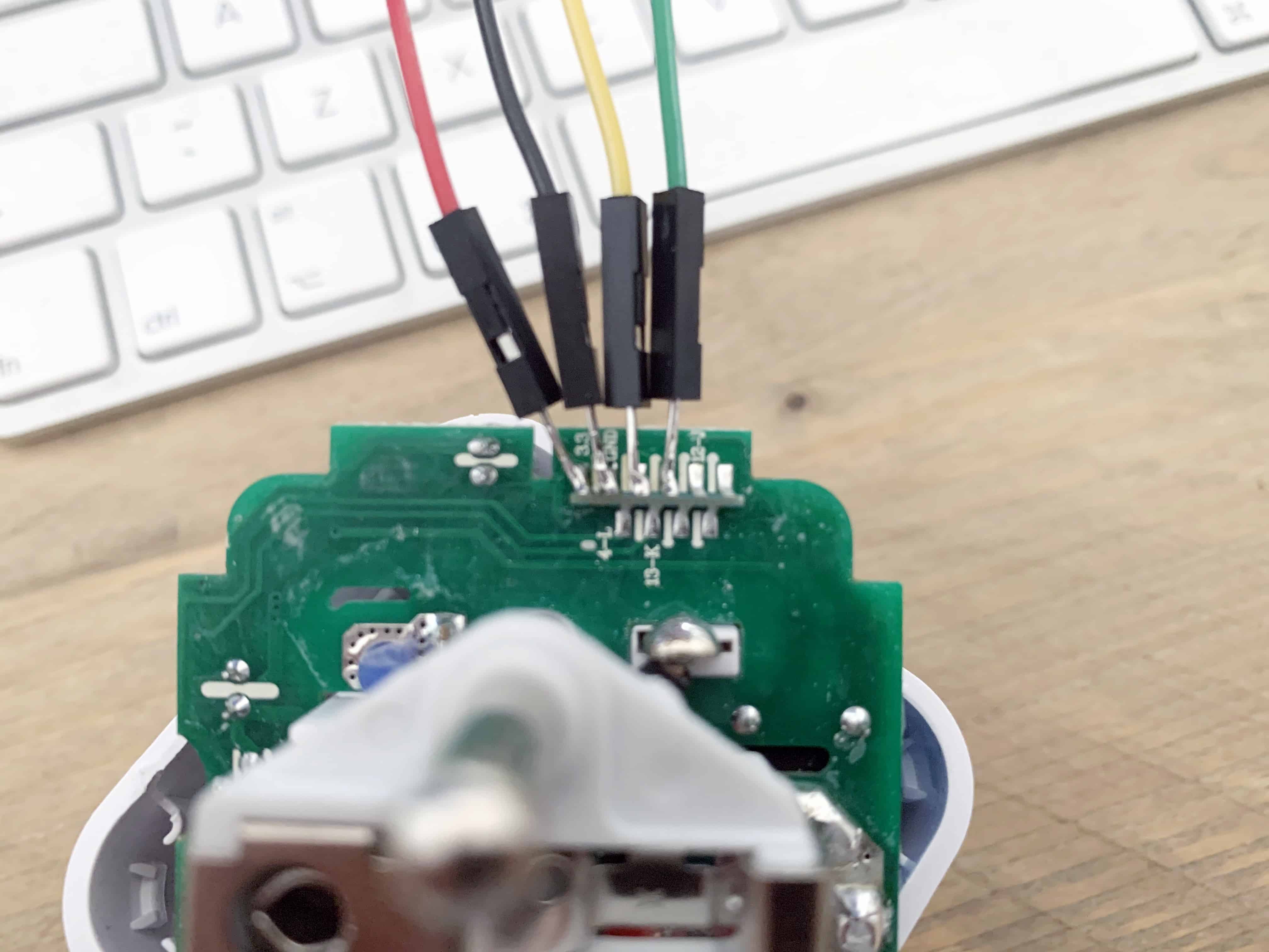
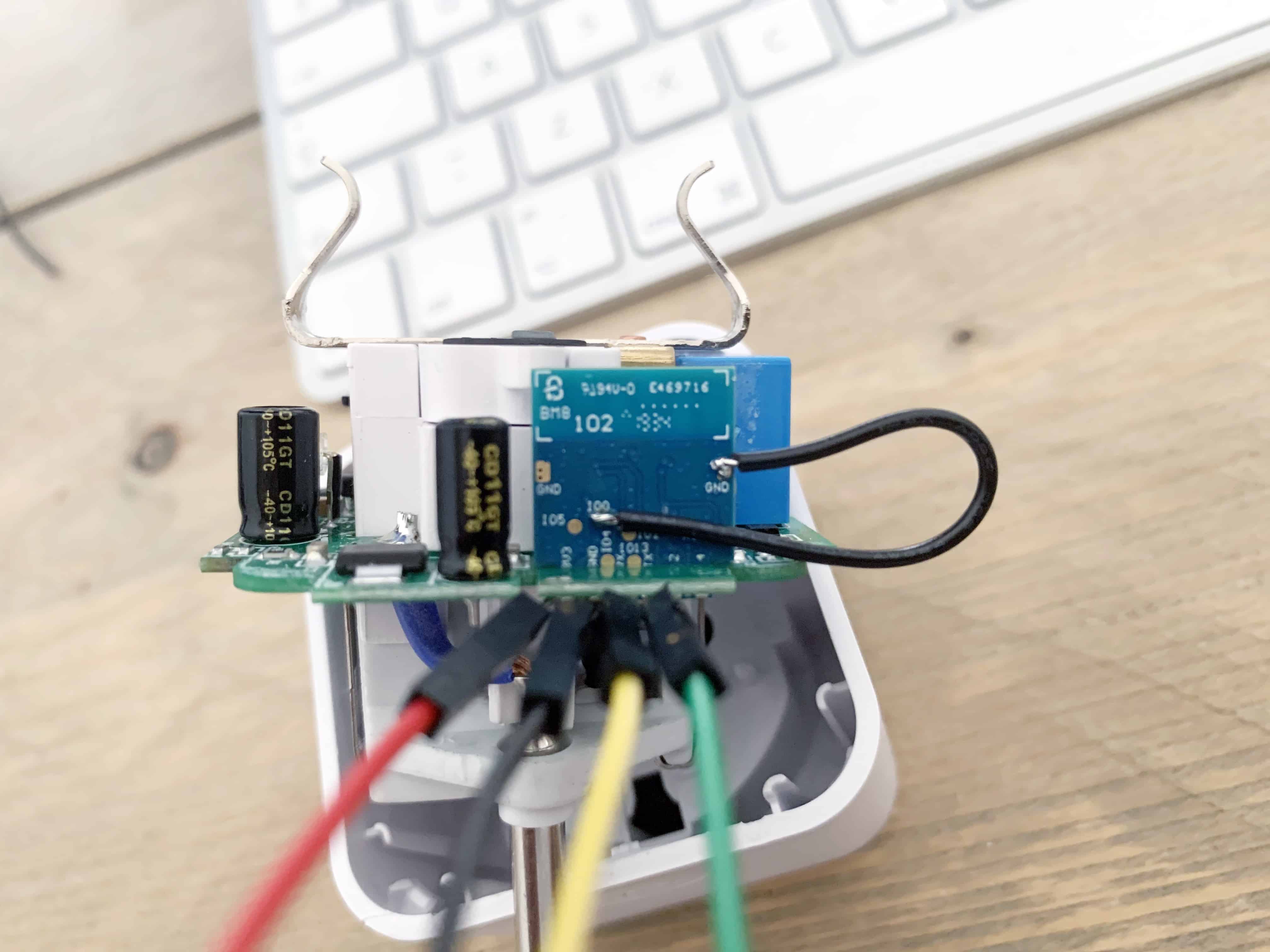
And this is how it will look like, when you have connected the cables as described in the scheme.
Flashing the ESP8285
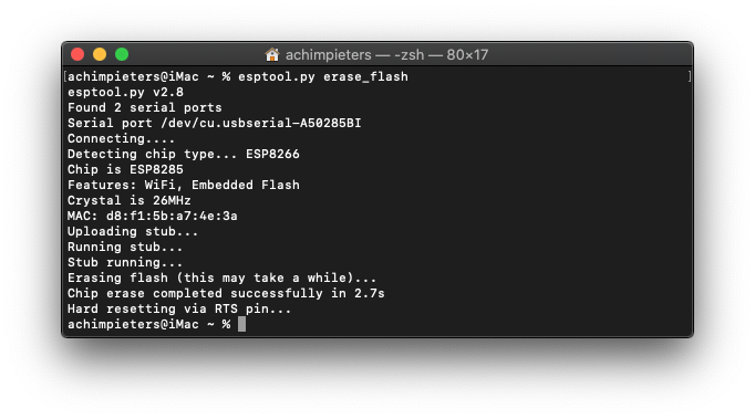
Now the great moment is here, will it work? First I am going to try to erase the Module, to do so I use the Esptool.py. for more information about this tool you can find here.
Erase flash memory from your ESP module:
esptool.py erase_flash
Yes! Succes as you can see that it detects the TYWE2S as an ESP8285 as suspected.
INSTALLING THE FIRMWARE
Before we go to the part where we actually upload the firmware to your ESP8285 we first need to get some other software. The Software we need is the Open Source FreeRTOS-based ESP8266 Software Framework, or sort ESP Open RTos. Furthermore we need a distribution system in this case we use GitHub as our online distribution system. And a smart manger that can install our Firmware, herefore we use LifeCycle Manager. We also need a good code editor like Atom.

ESP OPEN RTOS
ESP Open RTos is a community developed open source FreeRTOS-based framework for ESP8266 WiFi-enabled microcontrollers. Intended for use in both commercial and open source projects. Originally based on, but substantially different from, the Espressif IOT RTOS SDK.
You need two files to install the ESP Open RTos. You can download them here:
File name: rboot.bin
Version: 1.4.2
File name: blank_config.bin
Version: 1.4.2

LIFECYCLE MANGER
LifeCycle manger will Initial install, configure your WiFi settings and preform over the air firmware upgrades for any esp-open-rtos repository on GitHub. This is a program that allows any simple repository based on esp-open-rtos on esp8266 to solve its life cycle tasks. You can find more information about LifeCycle Manager here. You can download the binary file down here from my GitHub.
NEW RELEASE
LifeCycle Manager 2
Version: 2.1.2
otaboot.bin
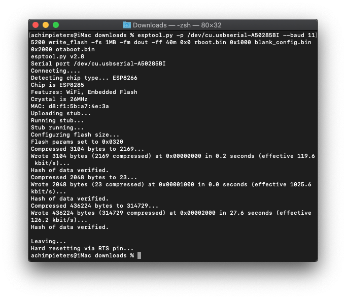
Normally, your ESPPort will be something like (e.g /dev/cu.usbserial-A50285BI). Then, set your device in flash-mode again, and flash the new firmware:
esptool.py -p /dev/cu.usbserial-A50285BI --baud 115200 write_flash -fs 1MB -fm dout -ff 40m 0x0 rboot.bin 0x1000 blank_config.bin 0x2000 otaboot.bin
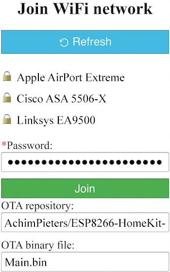
You must configure wifi network and OTA repository. To configure wifi settings, device generates its own Wifi in AP mode. You must connect to it in order to setup your wifi network. Simply take your iOS device, go to Setting -> Wi-Fi, and search a SSIDwith LCM- followed of last MAC address, connect to it, and wait a few seconds until a web appears showing you all wifi networks that the device has found. Select yours, and enter password. Don’t touch Join button yet!!
SOFTWARE INSTALLATION
Now, you must configure OTA repository as well. It’s very important that you configure it right, because you can not change it in the future (If you make a mistake, you must erase and flash device again).
OTA repository:
AchimPieters/ESP8285-Power-Plug
OTA binary file:
main.bin
To finish initial setup, click Join button and wait about 7 minutes until process finish (While installation is working, device doesn’t show anything, and buttons don’t work). After that, LED turns on for a couple of seconds and you will be able to add your accessory to your HomeKit ecosystem using Home App. LCM will install your HomeKit device on your ESP.
Now you can add your HomeKit Button by scanning the QR code below. To make the connection between your ESP and homkit takes a few seconds.

Once you have added the Contact Sensor you can assign the Contact Sensor, Door Sensor, Window Sensor, Garage Door Sensor,or Blind Sensor settings. When your connect your recent created device to HomeKit it will install it standard as a Contact Snesor. When you go to the settings you can change your Sensor to be a e.g “Door Sensor”.

TESTING THE HOMEKIT DOOR SENSOR HARDWARE
Pasting a selfmade sticker on my PowerPlug is the finishing touch.

Download all necessary files on GitHub.
DO YOU HAVE ANY QUESTIONS? LEAVE A COMMENT DOWN HERE.
Note: To produce and sell HomeKit compatible accessories, your company need to be certified for that (https://developer.apple.com/homekit/, If you’re interested in developing or manufacturing a HomeKit accessory that will be distributed or sold, your company must enroll in the MFi Program.) Espressif have their implementation of HomeKit framework, but it will give you it only if you have MFi certification (notice this text at the bottom of page you mentioned: Please note that the Espressif HomeKit SDK is available to MFi licensees only, and you need to provide the Account Number for verification purposes when requesting the SDK.).This project is a non-commercial implementation of HAP protocol, not meant for commercial use.
REFERENCE
Maxim Kulkin, esp-wifi-config (2019), Library to bootstrap WiFi-enabled accessories WiFi config, https://github.com/maximkulkin/esp-wifi-config Paul Sokolovsky, esp-open-sdk (2019), Free and open (as much as possible) integrated SDK for ESP8266/ESP8285 chips, https://github.com/pfalcon/esp-open-sdk Espressif Systems, esptool (2019), ESP8266 and ESP32 serial bootloader utility, https://github.com/espressif/esptool HomeACcessoryKid, life-cycle-manager (2019), Initial install, WiFi settings and over the air firmware upgrades for any esp-open-rtos repository on GitHub, https://github.com/HomeACcessoryKid/life-cycle-manager