
HomeKit
ESP8266 HomeKit Dual Lamps
Two lamps in one light fitting as one HomeKit accessory: a top light and a bottom light, two relays and a button that steps through the combinations. A test setup on an ESP8266.
- ESP8266
- HomeKit
- Safety notes
- 4 min read
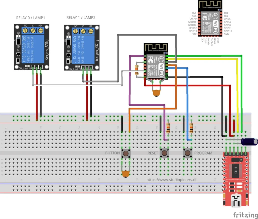
Two lamps in one light fitting, controlled as one HomeKit accessory. The top lamp and the bottom lamp show up as two separate lights in the Home app, so you can switch each one on its own, and a button on the device steps through the combinations.
This is a test setup. The build uses two relay modules and no mains voltage, and was made to check the code and the hardware.
What it does
| Feature | Details |
|---|---|
| One accessory, two lights | A single “Dual Lamp” accessory with a Top Light and a Bottom Light in the Home app |
| Two relays | Relay 0 switches lamp 1 (top), relay 1 switches lamp 2 (bottom) |
| Button | Steps through the four combinations of the two lamps |
| Identify | The top lamp stays on and the bottom lamp flashes, so you can find the accessory |
| Updates | Over the air, through Life Cycle Manager 2 |
| No cloud | Control stays on your own network |
The accessory name gets the last three bytes of the MAC address added, for example Dual Lamp-A1B2C3, so several of them can live in one home.
Hardware
| Component | Notes |
|---|---|
| ESP8266 module | An Ai-Thinker ESP8266 module of the ESP-12 type. See the ESP8266 pinout |
| 2 relay modules | Keyes SRD-05VDC-SL-C, one per lamp, each with NC, C and NO terminals |
| 3 push buttons | BUTTON, RESET and PROGRAM |
| USB-serial (FTDI) adapter | For flashing and for power in this test setup. Set it to 3.3 V logic |
| 470 µF capacitor | Across the supply, needed for stable operation when powering from the FTDI adapter |
| 100 nF ceramic capacitor | At the module, as drawn |
| Resistors | Pull-ups, as drawn |
In this test setup the module is powered from the FTDI adapter, which is not recommended for long-term use. The lamps are the two lamps of one light fitting, lamp 1 on top and lamp 2 below. Only the relay modules are connected in the test build, with no mains voltage.
Wiring and pins
The Fritzing diagram at the top of this page shows the build on a breadboard, with the pinout of the module in the corner. The pins the firmware uses are set at the top of main.c:
| Function | ESP8266 pin |
|---|---|
| Relay 0, lamp 1 (top) | GPIO12 |
| Relay 1, lamp 2 (bottom) | GPIO5 |
| Button | GPIO4, active low |
| LED (defined in the firmware, not drawn) | GPIO13 |
The relays are switched active-high. Use an FTDI adapter set to 3.3 V, because a 5 V adapter can damage the module. The Fritzing source of the diagram is in the repository as Resources/dual_lights.fzz.
Mains voltage
The test build has no mains connected. If you use the relays to switch lamps that run on mains voltage, disconnect the power first and only work on mains wiring if you know how.
Flash and install
The installation is the same as for the other ESP8266 HomeKit accessories on this site. The firmware runs on ESP-Open-RTOS with Life Cycle Manager 2, which sets up the WiFi and installs updates over the air. The full steps, from installing esptool to flashing, joining the LCM- WiFi network and pairing, are in ESP8266 HomeKit Blinds.
In the portal, use these values:
| Field | Value |
|---|---|
| OTA repository | AchimPieters/ESP8266-HomeKit-Dual-Lamps |
| OTA binary file | main.bin |
When the installation is done, scan the QR code the device generates in the Home app to add it.
Build from source
This repository includes the firmware source in the Dual_lamp folder: main.c, button.c and toggle.c. It builds with ESP-Open-RTOS. The Makefile uses the http-parser and dhcpserver extras, plus the wifi_config, cJSON, wolfssl and homekit components, with FLASH_SIZE set to 8, the dout flash mode at 40 MHz, and the HomeKit data stored at flash address 0x7A000.
The HomeKit setup code is set in main.c. Change it to your own before you use the device for real.
Firmware release
| Version | Date | Notes |
|---|---|---|
| 0.0.1 | 25 October 2019 | Initial release |
The release has a main.bin and a signature file, main.bin.sig.
Good to know
- This is a test setup and not a finished product.
- The HomeKit Accessory Protocol specification the firmware follows is the non-commercial version, for accessories you build yourself and do not distribute or sell.
- The repository is under the MIT licence.
Everything is in the ESP8266-HomeKit-Dual-Lamps repository on GitHub.
Related
 HomeKit
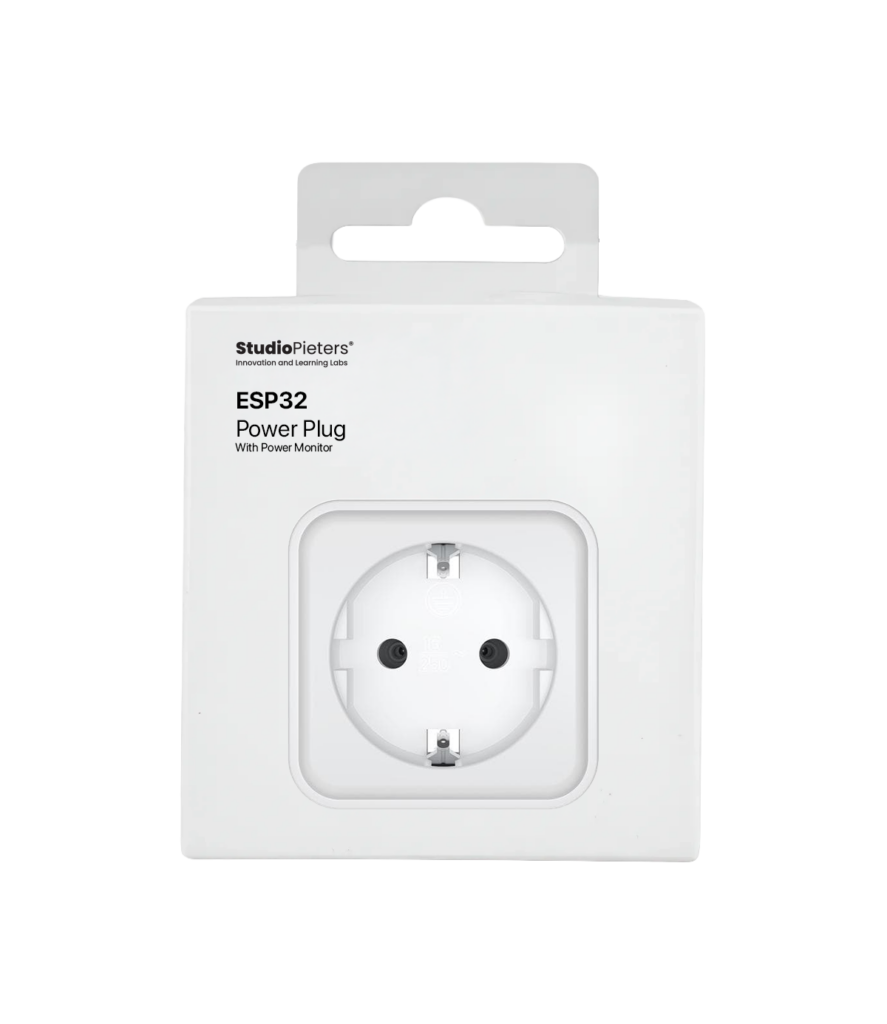
ESP32 Power Plug with Energy Meter
For many years, the Dutch retailer Action has sold affordable smart‑home devices under the LSC Smart Connect brand.
Read more
HomeKit
ESP32 Power Plug with Energy Meter
For many years, the Dutch retailer Action has sold affordable smart‑home devices under the LSC Smart Connect brand.
Read more
 HomeKit
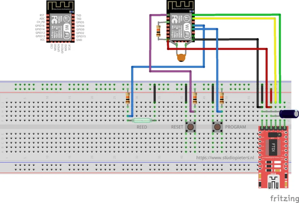
ESP8266 HomeKit Reed Contact Sensor
A HomeKit contact sensor on an ESP8266 with a reed contact and a magnet, for a door, window, garage door or blinds. A test setup from 2019.
Read more
HomeKit
ESP8266 HomeKit Reed Contact Sensor
A HomeKit contact sensor on an ESP8266 with a reed contact and a magnet, for a door, window, garage door or blinds. A test setup from 2019.
Read more
 HomeKit
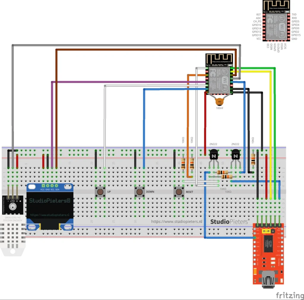
ESP8266 HomeKit Thermostat with OLED Display
A HomeKit thermostat on an ESP8266 that heats and cools, with a DHT22 sensor, a small OLED display and UP and DOWN buttons that change the set temperature by 0.5 degrees.
Read more
HomeKit
ESP8266 HomeKit Thermostat with OLED Display
A HomeKit thermostat on an ESP8266 that heats and cools, with a DHT22 sensor, a small OLED display and UP and DOWN buttons that change the set temperature by 0.5 degrees.
Read more
More HomeKit
Keep building.
Switches, sensors, plugs and blinds: more accessories that you build yourself and add to the Home app.
All HomeKit