
CNC
CNC 3018 PRO: Build, Control and Program It
A complete guide to the CNC 3018 PRO: the parts, the build, a Raspberry Pi with CNCjs and a camera, a Fusion 360 job and the bits to choose.
- Raspberry Pi
- CNC
- Archived
- 7 min read
Archived project
The GitHub repository for this project is archived: it is read-only and no longer updated. What follows describes the project as it was, so check for a newer alternative before you build it.
The machine has not been used for a long time.
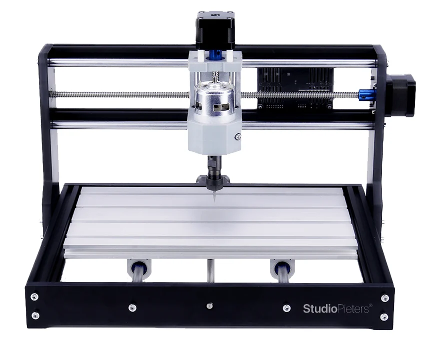
The CNC 3018 PRO is a small desktop CNC router. This guide follows the whole path: unpack the parts, build the machine, wire it, control it from a Raspberry Pi and prepare a job in Fusion 360. It was used to cut wood and thin aluminium.
The parts
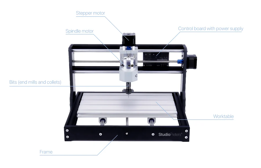
The kit comes in bags and boxes. This is the overview of the parts, and how they fit the machine:
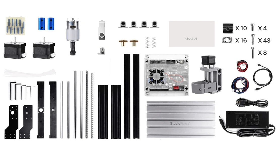
| Part | What it is |
|---|---|
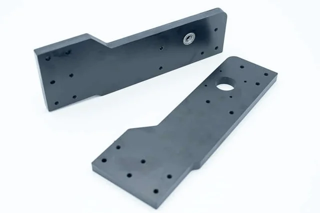
| Bakelite plates | The side plates and the rails of the frame |
| Linear bearing holders | Five holders with a bearing, for the moving axes |
| Aluminium profiles | Two kinds, for the frame |
| Lead screws and rods | Move the axes and guide them |
| Stepper motors | One for every axis |
| Aluminium table | A T-slot table for clamping the material |
| Z-axis carrier | With its stepper motor and the clamp for the spindle |
| Spindle motor | With a collet and a nut for the bits |
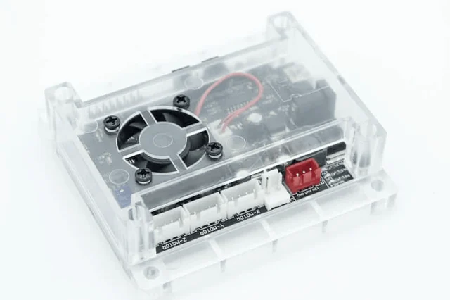
| Controller | A board with a fan in a transparent case |
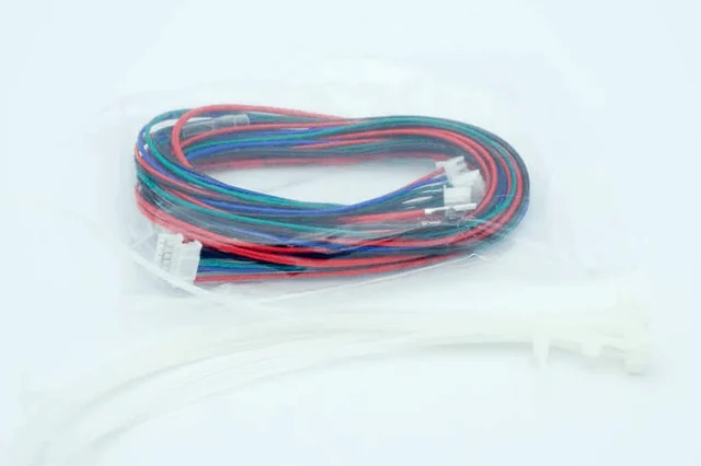
| Cables and cable ties | For the motors and the controller |
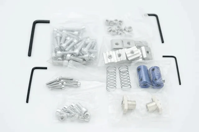
| Hardware | Screws, T-nuts, springs, couplings and Allen keys |
The parts one by one
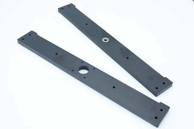
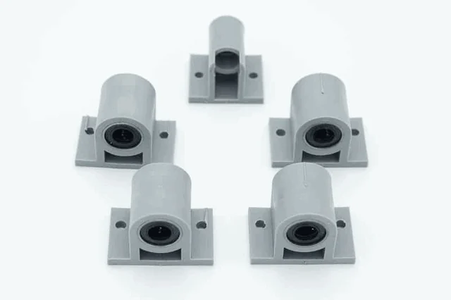
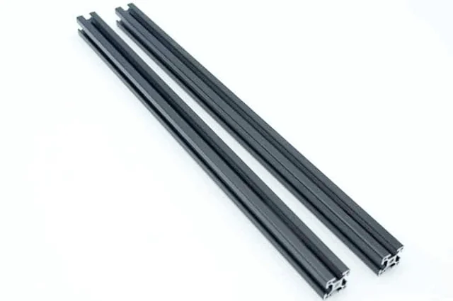
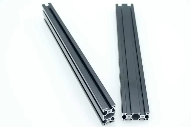
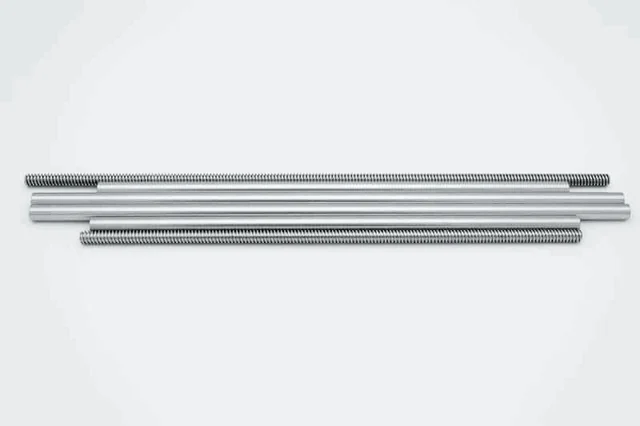
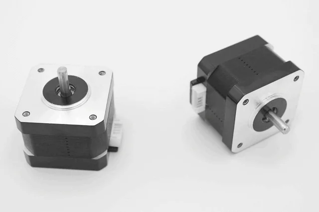
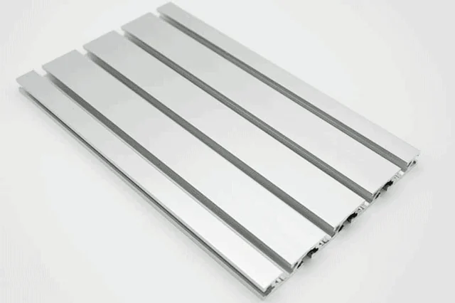
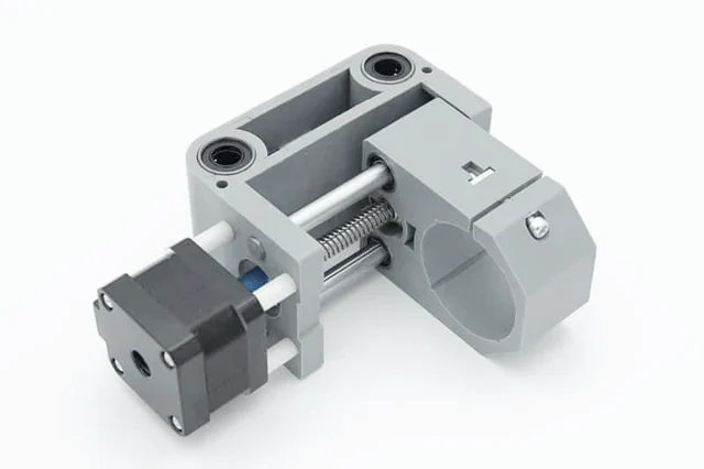
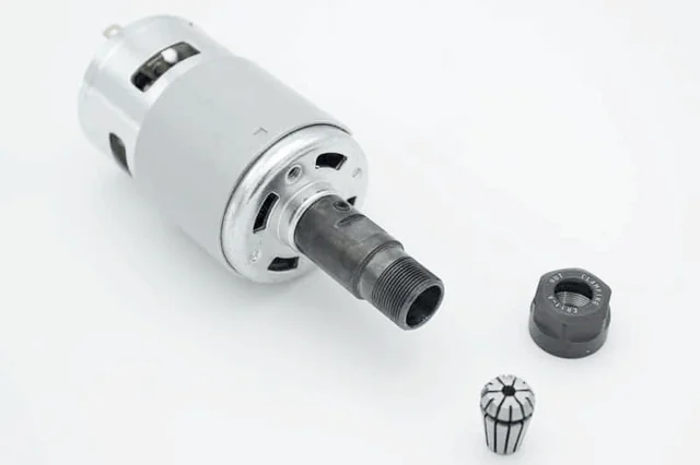
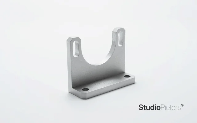
Build the machine
The steps below follow the photos of the build.
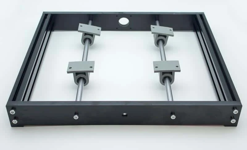
Step 1: the frame
Build the frame from the black profiles and fit the linear bearing holders on the rods of the Y axis.
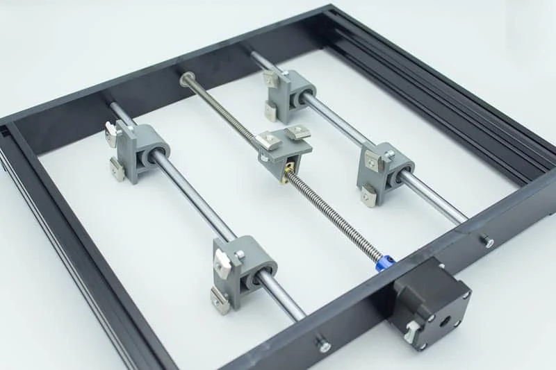
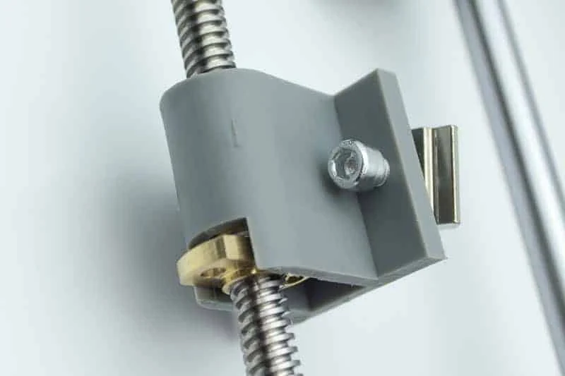
Step 2: the lead screw and the table carriers
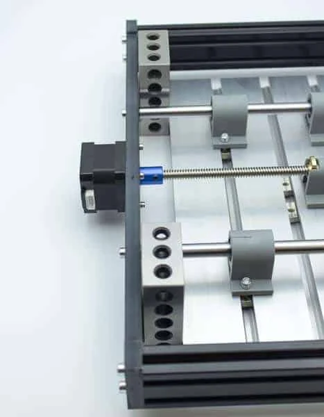
Fit the lead screw with its stepper motor and the nut in its holder, then the carriers for the table.
Step 2D: the table
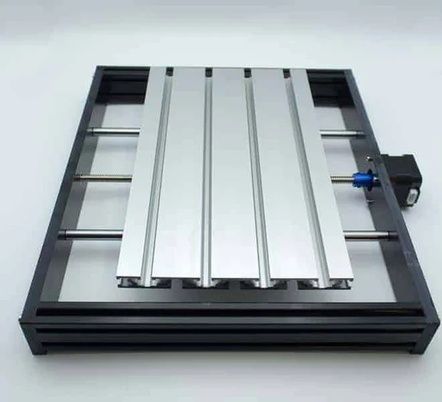
Fit the aluminium T-slot table on the carriers.
Step 3: the side plates
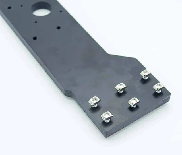
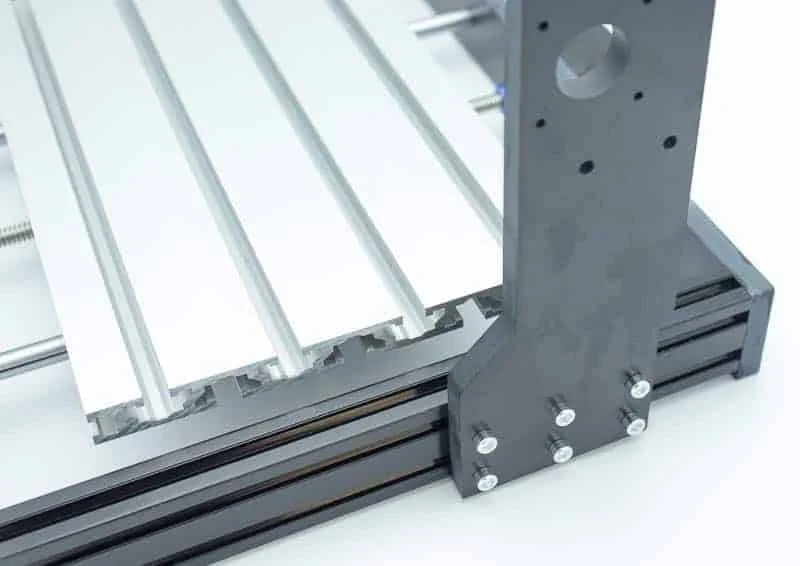
Put the T-nuts in the bakelite plate and fix the plates to the frame as the uprights of the machine.
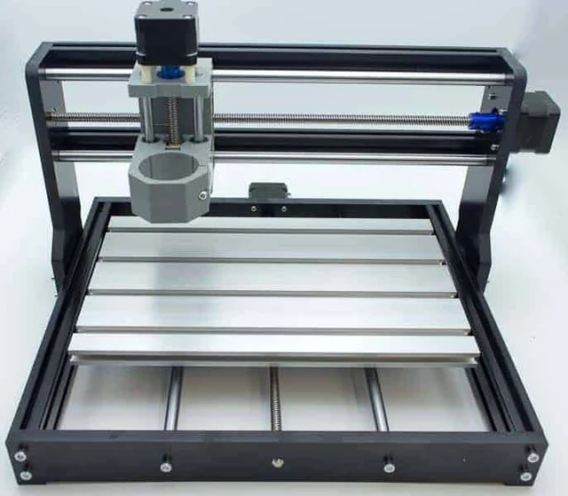
Step 5: the gantry with the Z axis
Fit the X-axis rods and lead screw with their motor, and the Z-axis carrier.
Step 6: the spindle motor
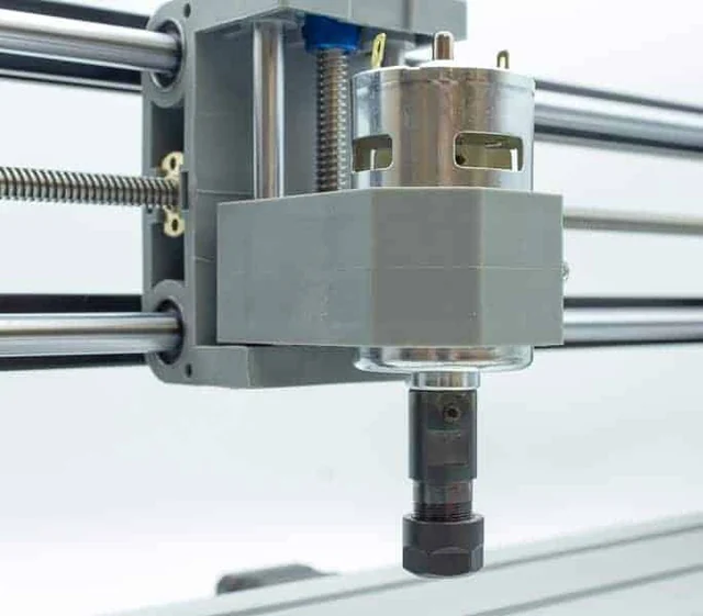
Put the spindle motor in the clamp of the Z axis.
Wiring the controller
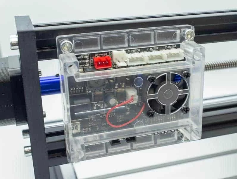
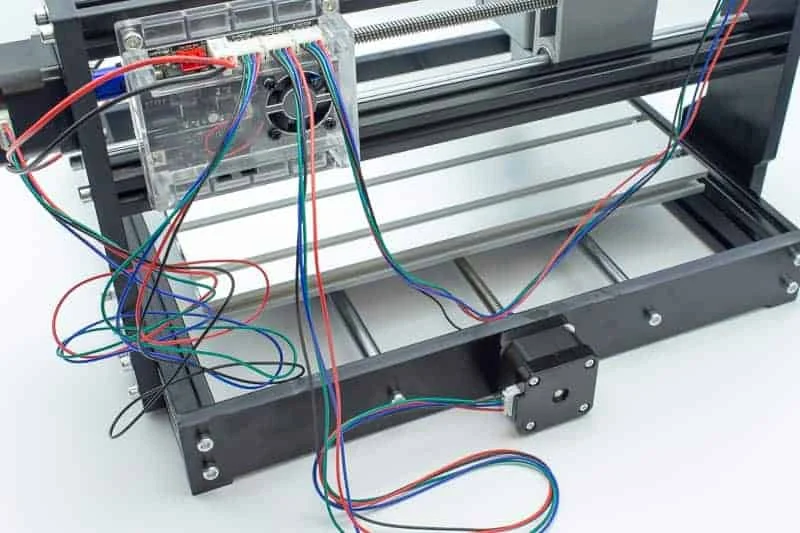
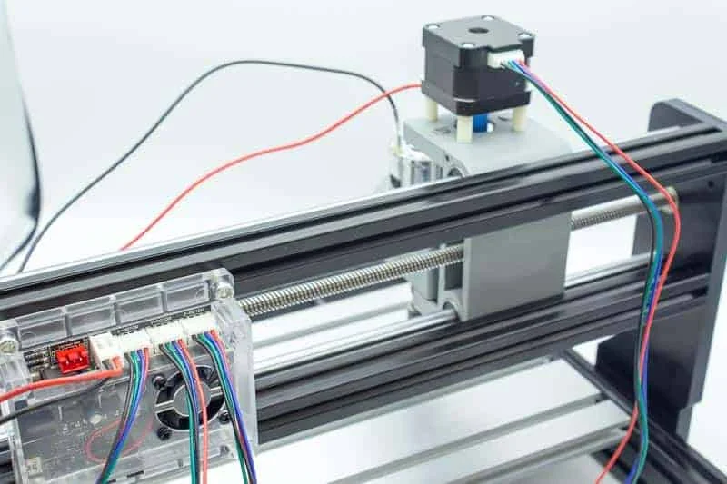
The controller sits in its transparent case on the side of the machine. Its connectors are marked X-MOTOR, Y-MOTOR and Z-MOTOR, and there is a red power connector.
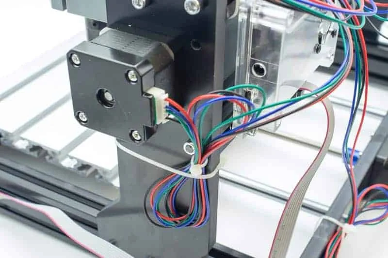
Plug in the motor cables, one to each axis, and route them along the frame.
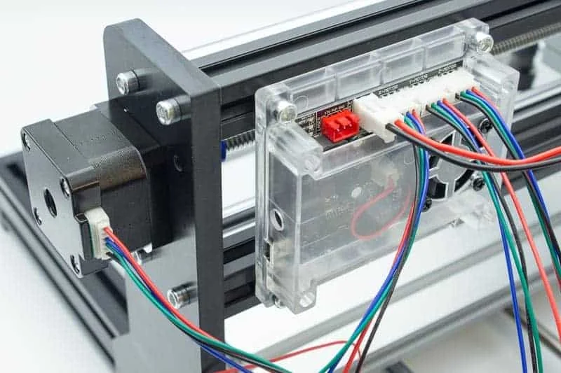
Tidy the wires
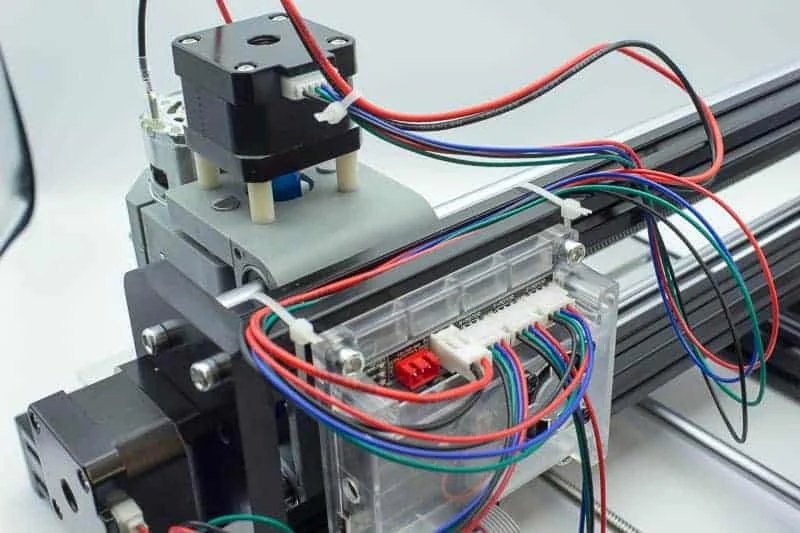
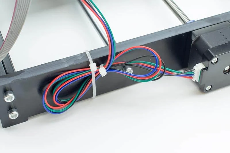
Bundle the loose cables with the cable ties, so they cannot catch in the moving parts.
Control it from a Raspberry Pi
Instead of a laptop by the machine, a Raspberry Pi 3 B runs CNCjs, a web interface for CNC controllers that run Grbl, Marlin, Smoothieware or TinyG. You open it in a browser on any computer in the house.
Prepare the SD card
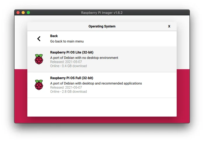
The screenshots show Raspberry Pi Imager 1.6.2:
- Choose Raspberry Pi OS Lite (32-bit), the version without a desktop, released on 7 May 2021 at the time.
- Choose the SD card as the storage.
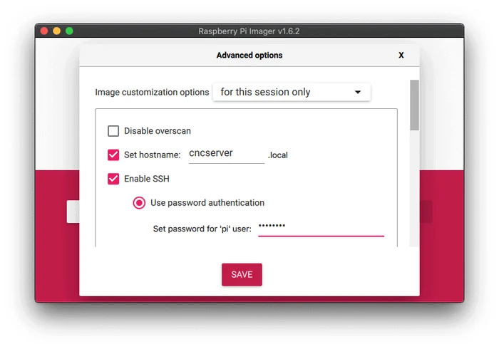
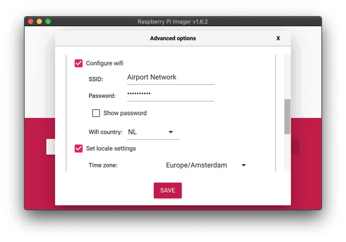
- Open the advanced options, set the host name to
cncserver, enable SSH with a password for thepiuser, and set your WiFi and the time zone. - Write the card.
Connect over SSH
Put the card in the Raspberry Pi and start it. After a minute you can log in from your computer:
ssh pi@cncserver.localThe first time, SSH asks you to trust the host. Type yes and then the password that you set.
Start CNCjs automatically
Install CNCjs as described in its own documentation. The service file below starts it at boot, and it expects the program at /usr/bin/cncjs. Save it as /etc/systemd/system/cncjs.service:
[Unit]
Description=A web-based interface for CNC milling controller running Grbl, Marlin, Smoothieware, or TinyG
Wants=network.target
Documentation=https://github.com/cncjs/cncjs

[Service]
Type=simple
User=pi
Group=pi
WorkingDirectory=/home/pi
Nice=5
ExecStart=/usr/bin/cncjs
# Use SIGINT to stop
KillSignal=SIGINT
# Auto restart on crash
Restart=on-failure
# Tag things in the log
SyslogIdentifier=cncjs

[Install]
WantedBy=multi-user.target
Then enable it and start it:
sudo systemctl enable cncjs
sudo systemctl start cncjs
A camera on the machine
A second service streams the Raspberry Pi camera with mjpg-streamer, so you can watch the job. It expects the program at /usr/local/bin/mjpg_streamer and uses the Raspberry Pi camera input:
[Unit]
Description=mjpg-streamer
Wants=network.target
Documentation=https://github.com/jacksonliam/mjpg-streamer

[Service]
Type=simple
User=pi
Group=pi
WorkingDirectory=/home/pi
Nice=5
ExecStart=/usr/local/bin/mjpg_streamer -i "input_raspicam.so"
# Use SIGINT to stop
KillSignal=SIGINT
# Auto restart on crash
Restart=on-failure
# Tag things in the log
SyslogIdentifier=mjpg_streamer

[Install]
WantedBy=multi-user.target
Both files are also in the gists of the author.
From model to G-code in Fusion 360
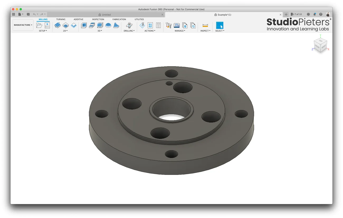
The repository has an example part, a round flange with holes, as a Fusion 360 file, Example.f3d. This is the path from the model to the G-code file, with the free personal version of Fusion 360.
1. Open the model
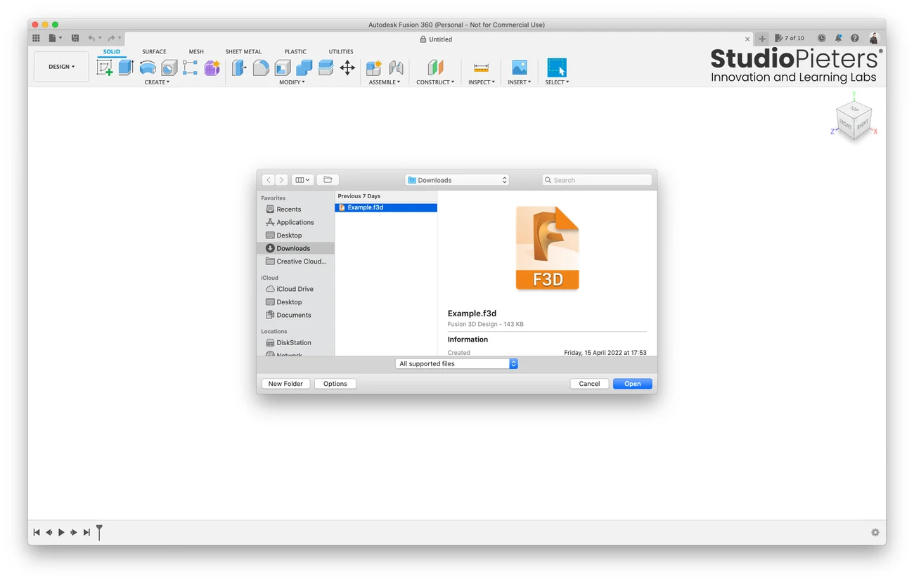
Choose File, Open and select Example.f3d. Then switch the workspace from Design to Manufacture, which shows the Milling tab.
2. Create a setup
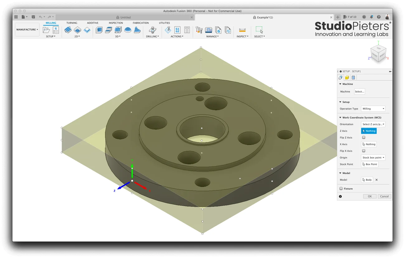
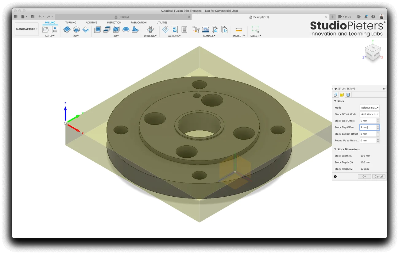
A setup describes the material and where the zero point of the machine is. Choose the orientation with “Select Z axis/plane and X axis”, and put the origin on the stock. In the example the stock is a box with an offset of 5 mm on the sides and 5 mm on top, which gives a block of 100 by 100 by 17 mm.
3. Make the bit
Open the tool library and add a flat end mill. The bit in the example has these values:
| Property | Value |
|---|---|
| Type | Flat end mill |
| Number of flutes | 3 |
| Material | HSS |
| Diameter | 3.175 mm |
| Shaft diameter | 3.175 mm |
| Overall length | 39 mm |
| Flute length | 17 mm |
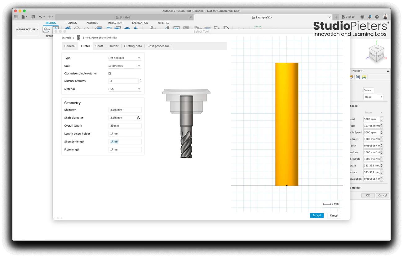
4. Pocket the flange
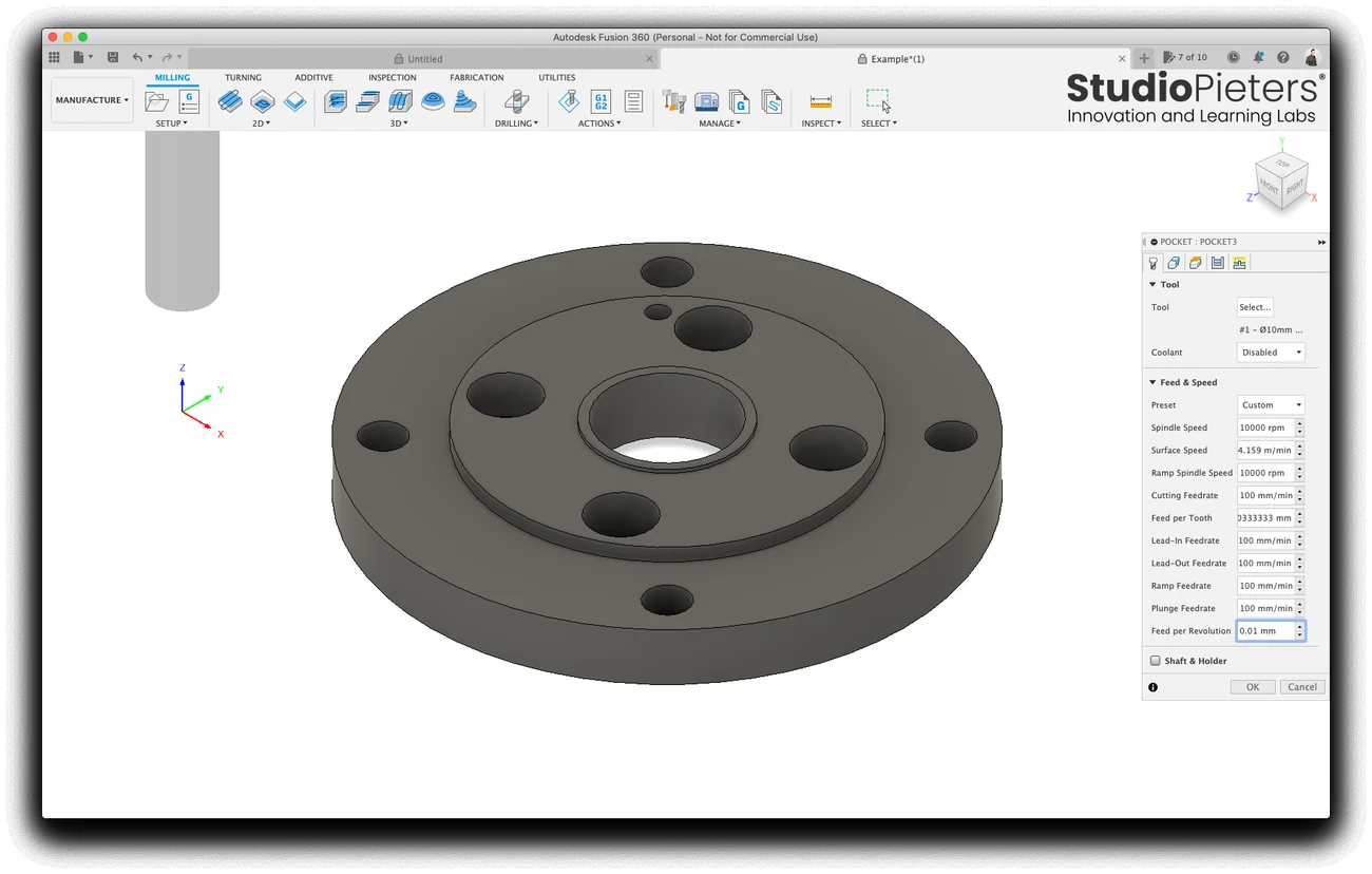
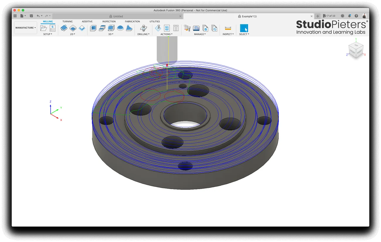
A 3D pocket removes the material around the part. The machining boundary is set to the silhouette of the model, and the coolant is disabled, since the machine has none. The speeds are low, for a small machine:
| Setting | Value |
|---|---|
| Spindle speed | 10000 rpm |
| Cutting feedrate | 100 mm/min |
| Plunge and ramp feedrate | 100 mm/min |
| Coolant | Disabled |
5. Cut out the outline with tabs
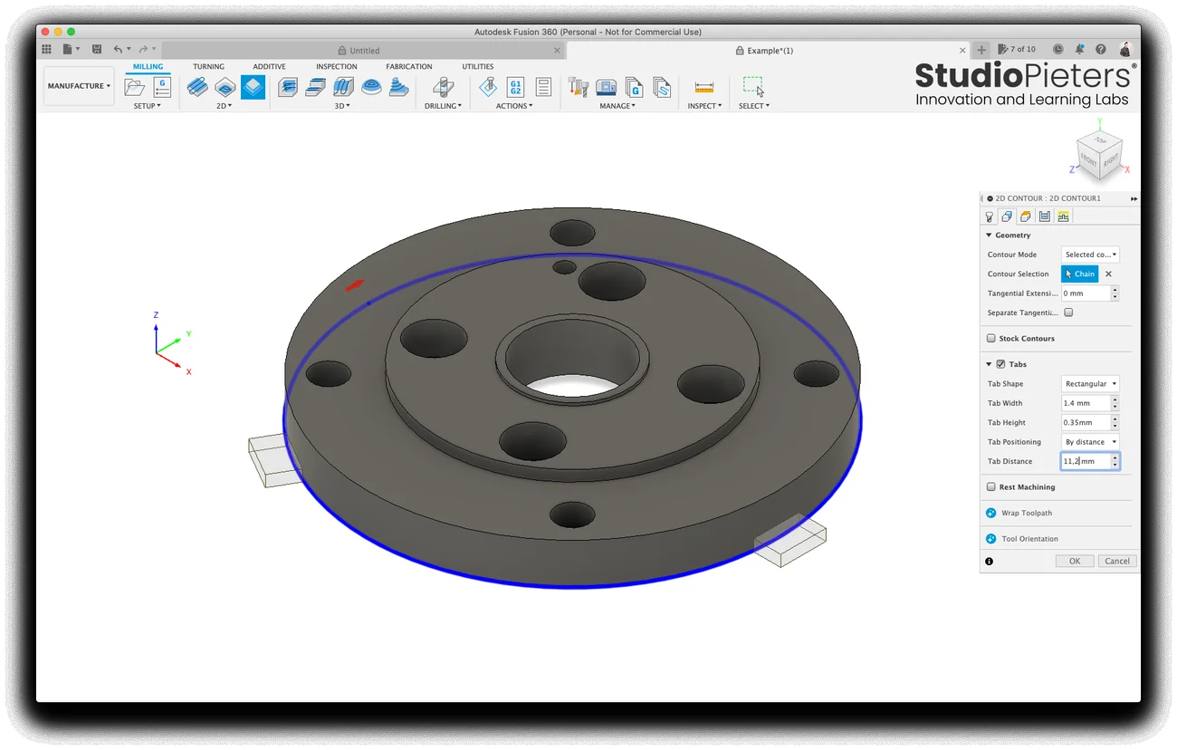
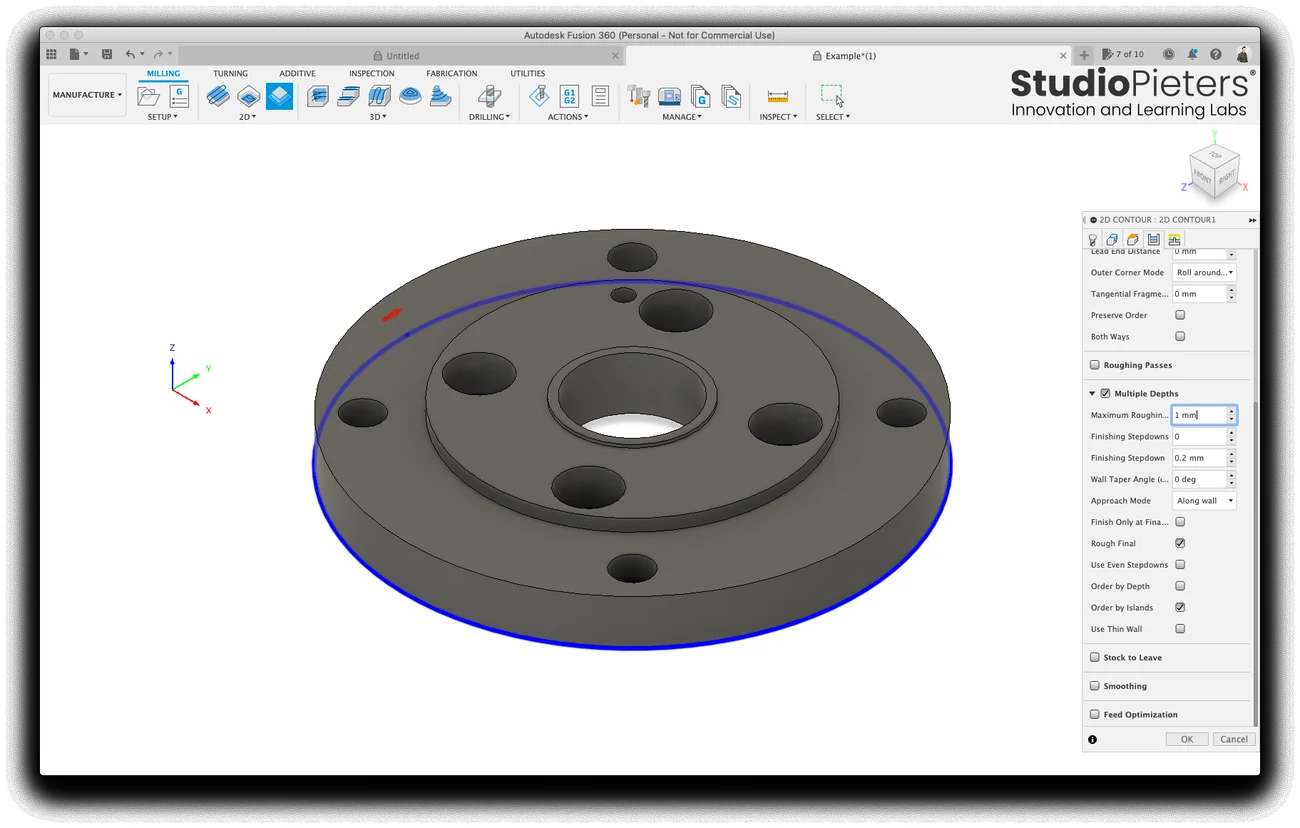
A 2D contour follows the outline of the part. Tabs keep the part attached to the stock until the end, so it cannot move while it is cut loose, and the contour goes down in steps:
| Setting | Value |
|---|---|
| Tab shape | Rectangular |
| Tab width | 1.4 mm |
| Tab height | 0.35 mm |
| Tab distance | 11.2 mm, by distance |
| Maximum roughing stepdown | 1 mm |
| Finishing stepdown | 0.2 mm |
6. Post the G-code
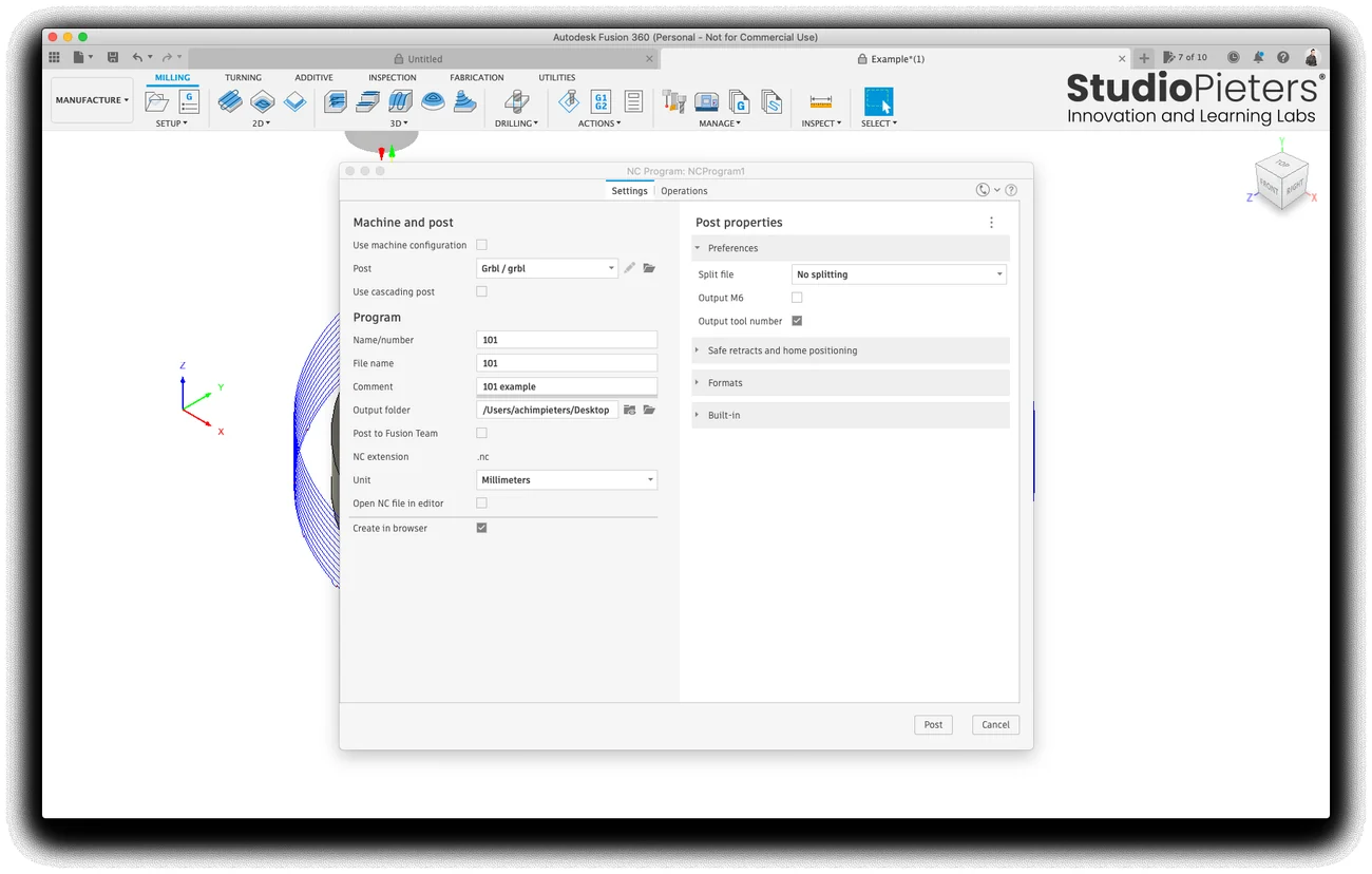
Choose Grbl as the post processor, since the controller runs Grbl, the unit millimeters and a program number. Fusion writes an .nc file.
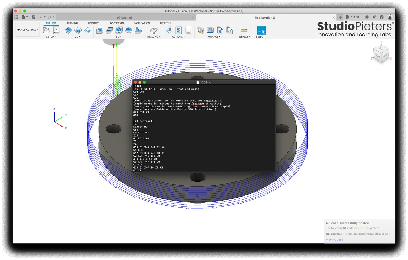
The comment in the file says that, in the personal use version, rapid moves are reduced to the feedrate of cutting, which can make a job take longer.
Choosing a bit
The shape of the bit decides what the cut looks like. These are the bits that are shown in the repository, each with a cut in wood.
Flat end mill and straight flute
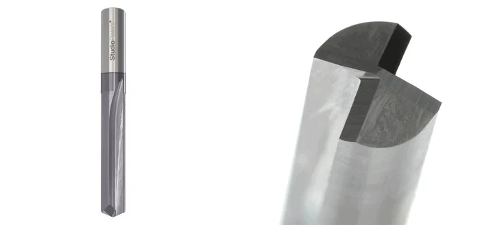
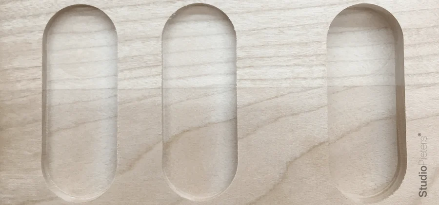
A flat end mill cuts a pocket with a flat bottom. A straight flute bit has flutes that run straight along the bit. The slots in the photo have a clean, flat bottom.
Ball nose
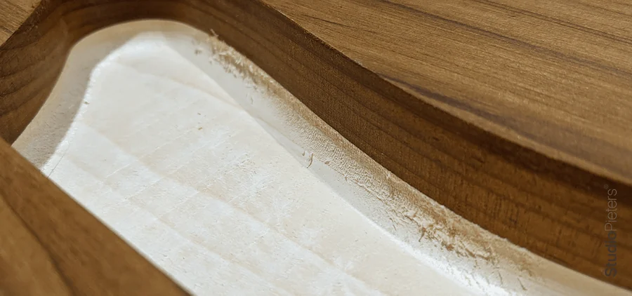
A ball nose bit has a round tip. It leaves smooth curves, which suits shapes that are not flat.

Up cut and down cut
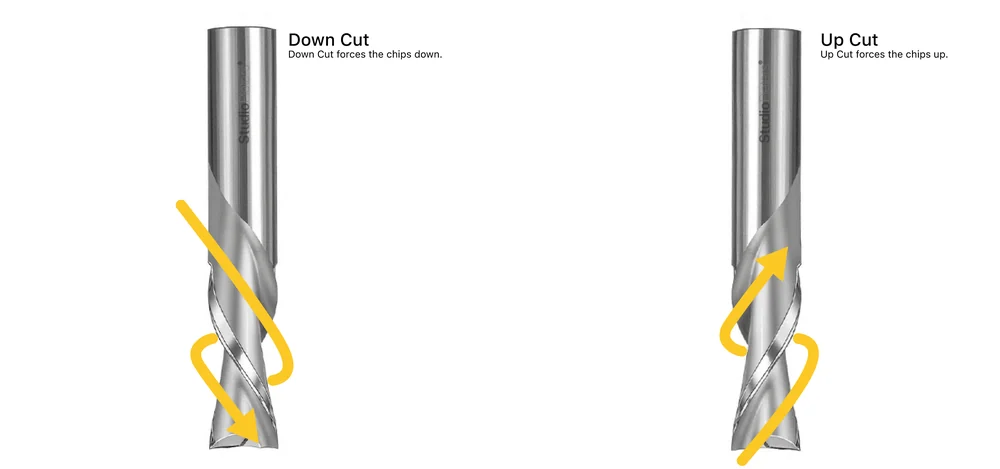
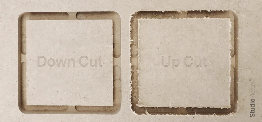
The spiral of the flutes decides where the chips go: a down cut bit forces the chips down, and an up cut bit forces them up. A down cut gives a cleaner top edge, and an up cut clears the chips out of the slot. The wood sample shows both.
V-groove and engraving
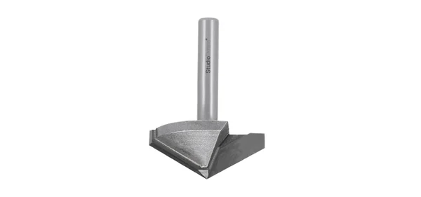
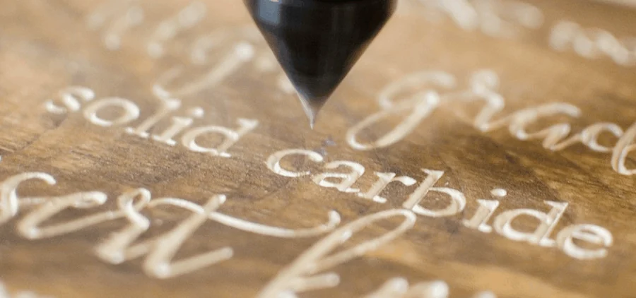
A V-groove bit has a pointed tip. It cuts letters and fine lines, and the width of the line depends on how deep the tip goes.


Surfacing
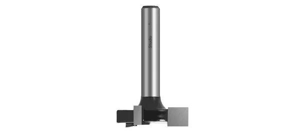
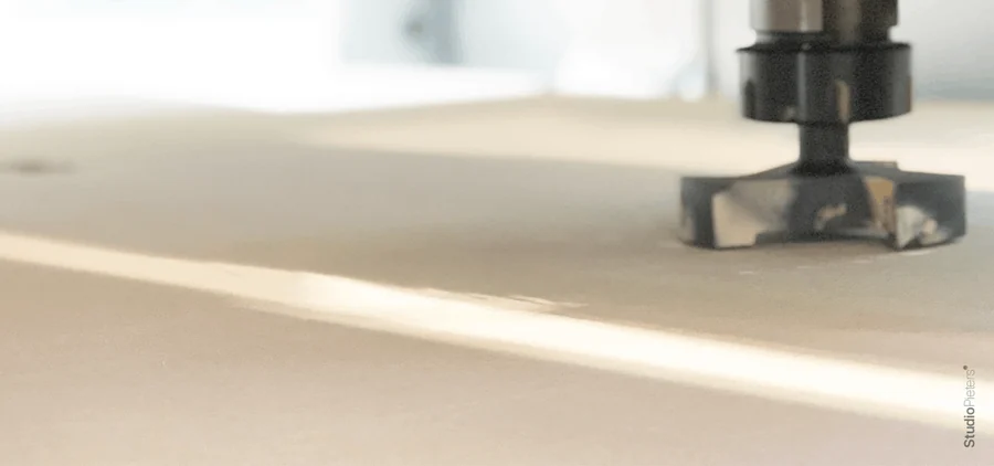
A surfacing bit is wide and flat. It makes the surface of the table or of the material level.
Good to know
- The machine was used on wood and thin aluminium.
- The repository holds the images and the Fusion 360 example,
Example.f3d, and is under the MIT licence. - Wear eye and ear protection and dust extraction when you cut, and never leave the machine alone while it runs.
The project is in the CNC-3018-PRO repository on GitHub.
Related
 Papercraft
The Stormtrooper Helmet: Pepakura Files for a Star Wars Fan
A Star Wars fan's papercraft collection, built around the First Order Stormtrooper helmet and the full armour, with more helmets and figures.
Read more
Papercraft
The Stormtrooper Helmet: Pepakura Files for a Star Wars Fan
A Star Wars fan's papercraft collection, built around the First Order Stormtrooper helmet and the full armour, with more helmets and figures.
Read more
 Software
ESP8266 HomeKit SDK in Docker: Build Your Own Firmware
Two Docker images with the ESP toolchain and ESP-Open-RTOS, to build ESP8266 HomeKit firmware on a Mac, from build to Apple Home.
Read more
Software
ESP8266 HomeKit SDK in Docker: Build Your Own Firmware
Two Docker images with the ESP toolchain and ESP-Open-RTOS, to build ESP8266 HomeKit firmware on a Mac, from build to Apple Home.
Read more
 Electronics
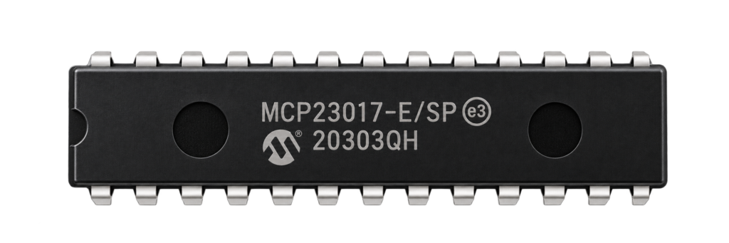
More Pins for an ESP8266 with an MCP23017
A test setup that adds 16 pins to an ESP8266 with an MCP23017 I/O expander on I2C, with a led as the example.
Read more
Electronics
More Pins for an ESP8266 with an MCP23017
A test setup that adds 16 pins to an ESP8266 with an MCP23017 I/O expander on I2C, with a led as the example.
Read more
More projects
Keep building.
Electronics, 3D printing and CNC builds, documented from the first idea to the last screw.
All projects