Not all European legislation for the standardization of USB-C for mobile devices, but also the switch of all kinds of electronics to USB-C will ensure that USB-C will become the standard. Look, but since the already well-known boards Arduino, Raspberry Pi, wemos boards, etc. have all already replaced the Micro-mini-USB ports with the USB-C port as standard.

USB-C
The USB-C is already the industry standard connector for transferring data and power. The company that developed the USB-C port is the same group of companies that developed its widely used predecessor, the USB standard, USB Implementers Forum. This forum consists of more than 700 companies including the big names Apple, Dell, HP, Intel, Microsoft, and Samsung. This is why the USB-C port has been so readily accepted by computer manufacturers. To set this in contrast, take the Lightning and MagSafe connectors, which were previously designed by Apple. This product was little used outside of Apple products and now that the USB-C has been released, they will soon disappear from the market.
USB-C is found in most recent mobile phones, tablets, and laptops. Even Apple uses the USB-C in some products, instead of their usual Lightening connector, for example with the new MacBook Pro. The market offers many adapters to combine your USB2, 3.0 and 3.1 with the USB-C. The only disadvantage of this is that you still need different cables for now. There are already many USB-C sticks available right now and the best part is that they are very easy to use. Just like with the standard USB stick, it must be plugged into the laptop or computer. Then the high-speed USB-C does the work for you, and you can get started right away with the allocated drive. The sticks themselves are available in different sizes, so you can tailor this to your preference.
USB-C Advantages
This section will have some more technical details, so keep your eye on it! USB-C help for the USB PD specification is a big step forward for device charging. USB PD can supply a device with 100 watts at 20 volts, compared to the 20–40 watts of the USB2.0 and 3.1. This is a big difference and ensures that charging devices can be done with much more ease. The USB-C port, like the reversible Lightening plug, can be inserted in any way due to its symmetrical design. Most USB-C ports are built on the USB 3.1 data standard and can theoretically achieve data speeds of up to 10Gbps. This is twice as fast as USB 3.0 as well as the first generation USB 3.1 which reached maximum speeds of 5Gbps.

USB-C also supports Intel’s Thunderbolt 3.0 data transfer technology and can achieve data speeds of up to 40Gbps. These improved data speeds make it possible to send videos over the same connection. Using the USB-C’s “Alt mode”, videos can be projected over the same connections on HDMI, DisplayPort, VGA, TVs, projectors and other forms of video connections. To summarize this briefly, USB-C is suitable for almost all devices that are released at the moment. With its speeds, high capacities and the fact that it can be made suitable for older models of laptops and phones, USB-C is the new technology to watch. We recommend that you do not lag behind in this development and ensure that your new devices are equipped with the new USB-C port, so that you too can enjoy the convenience, speed, and diversity of this technology.
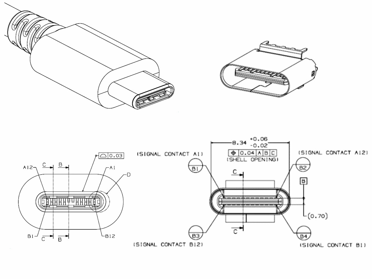
USB-C Connectors
This is the connector pinout from Wikipedia:
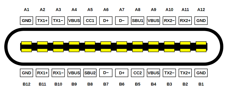
It looks quite daunting, but we actually don’t care about most of those pins for our application:
- TXn+, TXn-, RXn+, RXn- pins are for USB 3 Super speed, so we can ignore them.
- SBU1/2 pins are for side band use (used for low speed communication when the port is used for something like DP or HDMI), so we can also ignore them.
That leaves us with these pins –
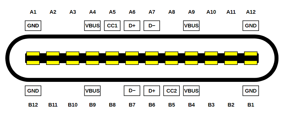
Much more manageable. Most of them are pins we already know and love – VBUS, D+, D-, GND. Except they are all doubled/quadrupled now to support reversible insertion. They can (and should) all be shorted together. The only new pins are CC1 and CC2 (channel configuration), and they do a few things:
- Pull down resistors on the device side tells the host that a connection has been made with a device, and VBUS should be turned on. Unlike Type A, in Type C VBUS is never energized until a host knows a device is there, because the user may plug two hosts into each other, and terrible things would happen if they are permanently live.
- On the device side, one of them will read as ground, and the other some higher voltage. This tells us the cable orientation. It’s important for 3.0/Super speed operations, but we don’t actually care about orientation for 2.0, since we are shorting all the other pins together! I will refer to the non-ground one as CC from now on. Though it can be physically on either CC1 or CC2 depending on orientation (and we must account for both possibilities, otherwise our device will only work with cable inserted one way). No, we cannot short them.
- The CC voltage is used to determine how much current is available from the upstream port, and whether there is a connection. This voltage is determined by a voltage divider between host and device.
- If we want to do Power Delivery (we need more than 5V@3A). The communication also happens on the CC pin.
The standard requires that CC1 and CC2 be pulled down to ground on the device side with a 5.1k ±10% Ω resistor each. With a basic C-C cable, only one will be connected to the host. Which will have different valued pull-up resistors to indicate how much current it can supply – 56 kΩ, 22 kΩ, or 10 kΩ to 5V, or an equivalent current source, or equivalent pull-ups to 3.3V.
So in the end, the whole circuit looks like this:
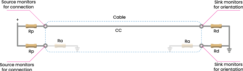
In a basic USB 2.0 3A cable, Ra doesn’t exist, but fancy cables that support higher speeds or higher currents will have them to power electronics in the cable, so they can tell the host their capabilities. On the device side, we don’t care about that, but that’s the reason we can’t short the CC pins and just use one resistor. Raspberry Pi Foundation did that with early revisions of the Raspberry Pi 4, and it didn’t end well for them. Don’t be like them.

In terms of determining how much current you can draw, just read the CC voltage (remember that it’s the highest of CC1 and CC2). Thresholds are as follows:
| Detection | Min Voltage | Max Voltage | Threshold |
| vRa | -0.25 V | 0.15 V | 0.2 V |
| vRd-Connect | 0.25 V | 2.04 V | |
| vRd-USB | 0.25 V | 0.61 V | 0.66 V |
| vRd-1.5 | 0.70 V | 1.16 V | 1.23 V |
| VRd-3.0 | 1.31 V | 2.04 V |
So what that means is:
- [0V – 0.2V]: No connection (we only care about this if the device is self-powered, because in a bus-powered device, the fact that we have power and the firmware is running means there is a connection)
- [0.2V – 0.66V]: Standard USB current available, the host either has no high current capability, or we are connected to a legacy host with an A-C cable.
- [0.66V – 1.23V]: 1.5A available
- [1.23V+]: 3.0A available
In practice, most laptops will supply 1.5A or 3.0A, most wall warts will supply 3.0A, and phones (if we use them as host) will support standard USB. The CC voltage may change over time and should be continually monitored. When it changes, the device has 60ms to be compliant with the new advertised current limit.

If we are using a USB-A power supply with an A-C cable, it will always show vRd-USB because the pull-ups are actually inside the cable. Since a USB-A host knows nothing about CC signals, and a compliant A-C cable can’t assume the host can supply more. There ARE non-compliant cables that do advertise high current support to device without checking with host. They are a fire risk and should never be used. Fortunately they are less common now in 2021. So if we want to draw more current from a legacy power supply, we have to go back to the pre-Type-C madness on data lines.
Putting It All Together (aka TLDR)
With that, we arrive at the schematics for using a Type C port as a micro-B replacement.
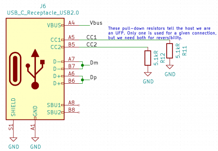
Vbus, D+, D-, and GND are used just like in legacy connectors. CC1 and CC2 must have a 5.1 kΩ pull-down each. If you want to take advantage of the new Type C current advertisement mechanism, they should be routed to ADC pins on your microcontroller. But if you don’t need that, leaving them alone with just the pull-downs is perfectly fine, too, and it will act just like a standard Type B port electrically. Note that I am using a connector with only the USB 2.0 pins. If you are using a fully-featured connector, all other pins can be left unconnected.
Choosing a USB-C Connector
Now that we have decided to add USB-C to our project, we need to pick a connector to use. It’s not easy – there is a huge variety on the market, and some are much harder to use than others. Generally, they are one of these four types.
Full Featured All SMT
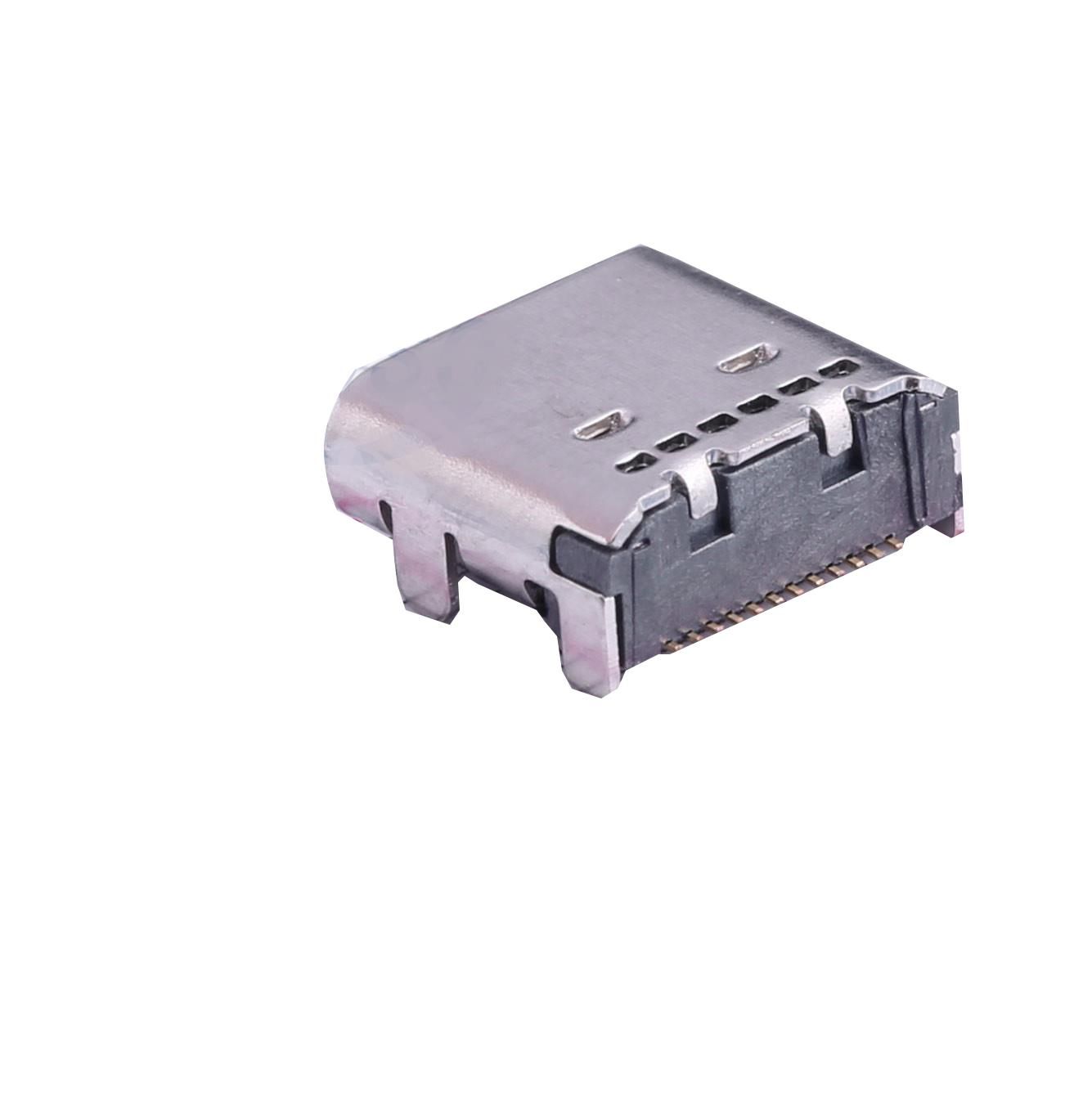
The first type is a fully featured connector with two rows of SMT pads. They are probably the most difficult to use for hobbyists. Because there is no way to inspect/fix the inner pads, and at ~0.3 mm pitch, those pads are very close together, and may short if your reflow process isn’t absolutely perfect. If you are getting your boards professionally assembled, this may be OK, but there’s no need to risk it if you don’t need USB 3.0 Super speed.
Here is one example: Korean Hroparts TYPE-C-31-M-05.
Full Featured 1/2 SMT 1/2 TH
And then we have connectors where the back row uses through-hole pins instead of pads. They are probably easier, but the pins are very close together, and it seems like a huge hassle.
Example: JAE DX07S024XA8R700.
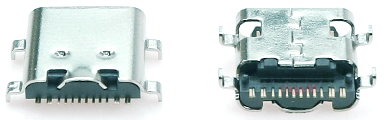
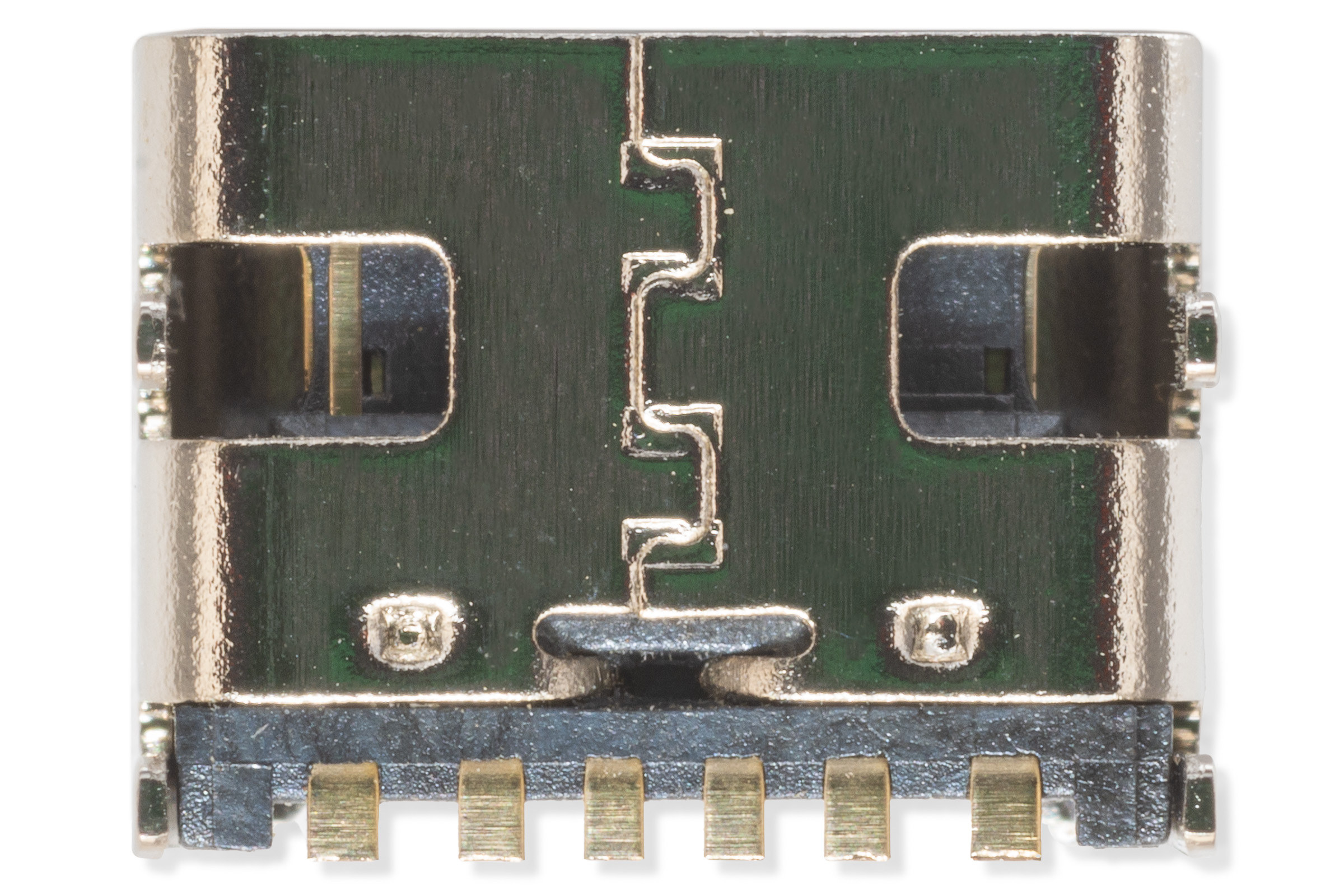
USB 2.0-Only SMT
And then we have connectors that omit all the pins not required for USB 2.0, and we end up with a connector with just one row of SMD pads, with reasonable spacing. This option I believe works the best for our applications, and my chosen connector is the Korean Hroparts TYPE-C-31-M-12
Power-Only SMT
If we don’t need data transfer at all, there are even simpler connectors that only have power and the CC pins (so we can determine how much current we can draw).
Example: Korean Hroparts TYPE-C-31-M-17.
USB-C Current
Continuous
But it basically boils down to this (as I understand it) – there are 3 types of ports. Standard Downstream Port (SDP) which is data only with no high current capacity, a Charging Downstream Port (CDP) which is data + 1.5A, and a Dedicated Charging Port (DCP) which is 1.5A with no data. One possible detection algorithm is to apply 3.3V to D+, and read D-. If it’s 3.3V, we have either CDP or DCP (otherwise SDP). Then we do the same, but reversed (apply voltage to D- and read D+). If D+ reads 3.3V, we have a bidirectional short between D+ and D-, which means we have a DCP. Otherwise, it’s a CDP.
And remember that you have to multiplex it with data, if you also want to do data transfer. If you want to support proprietary implementations, that’s a whole other can of worms. Both Apple and Sony use resistive dividers on data lines that can be read with an ADC. Quick Charge I believe requires a dedicated controller.

Without either CC showing 1.5A/3A or BCS showing CDP or DCP, we have standard USB current, and that’s a lot more complicated. In this case, you are allowed to draw 500mA only if your device cannot enumerate. If your device does enumerate, it must draw a maximum of 100mA until negotiated otherwise with the host as part of the enumeration process (up to 500mA).
Startup Current
So either Type C current advertisement or BCS tells us the maximum continuous current, but what about peak current at plug-in, when all the capacitance charge up? The spec allows for 10µF on Vbus (Table 4-3: VBus Sink Characteristics) or equivalent. What that means exactly is not 100% clear, but most people take it to mean that the initial current spike above the max continuous current allowed. When integrated over time, should be no more than 50µC, which is what a 10µF capacitor will draw at 5V. So if we have a huge capacitor behind a regulator, that would count, too, unless our regulator is current-limiting.
It does NOT mean we can’t have more capacitance than that. What that means is if we have more capacitance, we have to limit the inrush current so that they don’t appear as “naked” capacitance on Vbus (it may trigger overcurrent reset from the host). If we limit the charging speed of our capacitance to the max continuous current, we can have as much capacitance as we want. Fortunately, there are many chips (usually called USB Power Distribution Switches) that can handle this for us. For example, the Diodes Incorporated AP2162/2172.
Current Slew Rate
This one is a bit harder to design for, and is probably more practically verified on the prototype rather than ensured by design. The maximum current slew rate (dI/dt) is 150mA/us, both on ramp up and down. This is the iLoadStepRate(max) in the spec, and the reason it’s limited is that too much dI/dt can cause unacceptable Vbus voltage drop on the host due to inductance in the power supply path. If your design is exceeding this, it needs more capacitance (potentially requiring the use of a current-limiting switch, as described above).
Suspend Mode
A compliant device must implement suspend mode. In short, if there is no traffic on the data bus for 3ms, the device has 7ms to enter suspend mode where it must draw no more than 2.5mA. This may be difficult to implement if you don’t do USB yourself, but for example, the Silicon Labs CP210x USB-UART chip has suspended outputs for this purpose. The microcontroller can monitor it, and turn into go into sleep mode if/when it goes high. This requirement may be ignored if either CC indicates 1.5A/3.0A, or the host is a CDP/DCP port as detected through BCS.
USB-C PCB Design
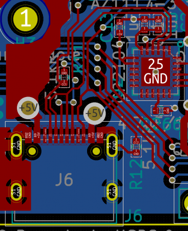
It depends on what connector you choose, but in my case it’s pretty simple. All the shorting does make it a bit more complicated, but still easily doable on 2 layers, which is a requirement for this project due to cost-sensitivity (most of my other projects are 4 layers now). For routing the data traces, standard rules apply (this is not specific to USB-C). They should be routed close together, with minimal via’s and parallel runs of traces on another layer. Do we need impedance-controlled routing? Well, if you have a 4 layer board, and you get free impedance control from your fab (like JLC), might as well do it. But whether that’s necessary or not depends on speed (edge rate) and trace length.
The general rule of thumb is if the edge rate divided by signal travel time is smaller than 6, we need to think about treating it as a transmission line (with controlled impedance). USB minimum edge rates are 75ns for Low Speed, 20ns for Full Speed, and 500ps for High Speed. That gives us a maximum propagation time of 12.5ns, 3.33ns, and 83ps respectively. Velocity of propagation is ~0.6c, which gives us a maximum trace lengths of 2.2 m, 60 cm, and 1.49 cm respectively, without having to worry about transmission line effects. In practice, that means we don’t really need to worry unless we are doing High Speed (or we have very long traces).

Your result will be different depending on the fab, dielectric, and the stack up they use. There should always be a solid ground plane underneath the transmission line, and no other trace should be within 3x the width of the traces. CC lines are low speed, and you can do whatever you want with them (within reason…).
Reference
dubiouscreations, Designing with USB-C: Lessons Learned, https://dubiouscreations.com/2021/04/06/designing-with-usb-c-lessons-learned