
Reference
The Ultimate Guide to the BL0937 Energy Meter IC
The BL0937 single-phase energy meter IC: labeled pinouts of the SOP8 package, datasheet limits and package dimensions, the pulse formulas, a typical circuit, ESP32 pulse counting, calibration, and the safety rules of a mains chip.
- Single-phase energy meter
- Pulse outputs CF and CF1
- 3.3 V supply
- Under 0.5 % error
The BL0937 is a single-phase energy metering chip from Shanghai Belling, made for smart sockets, power strips and appliances. It measures the voltage across a small shunt resistor (the current) and across a resistor divider on the mains (the voltage), multiplies them inside, and gives you the result as pulse trains: one pin pulses with the active power, another pulses with the current or the voltage RMS. A microcontroller only has to count pulses. It needs no crystal (it has an internal 2 MHz oscillator), no external ADC and almost no other parts.
This guide covers both sides of the chip with every pin labeled on your own drawing, the dimensions of the SOP-8 package, the electrical limits, the pulse formulas, the typical circuit, wiring to an ESP32, a pulse-counting sketch, calibration, and the traps. The chip is used on mains voltage, so read the safety notes before you build anything.
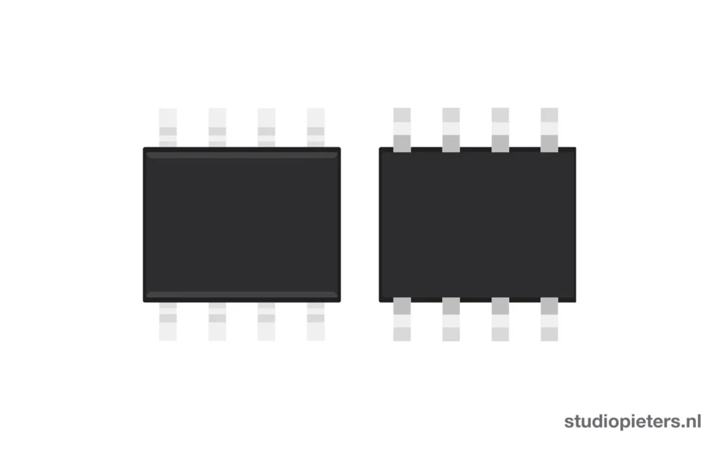
All chip data comes from the Belling BL0937 datasheet (V1.02). Your drawing is an 8-pin SOP; the file is named BL0942, but the BL0942 has no 8-pin package, so the drawing is used here for the BL0937. The pin 1 mark is added, because the drawing has none.
What the chip does
Inside the BL0937 are two sigma-delta ADCs (one for current, one for voltage), a 1.218 V reference, a power supply monitor, a digital signal processor that multiplies voltage and current, and a digital-to-frequency converter. The results come out as frequencies: CF carries the active power (and shows an over-current alarm), CF1 carries the current RMS or the voltage RMS, chosen with the SEL pin.
| Item | Value |
|---|---|
| Chip | Belling BL0937, single-phase energy meter IC with integrated oscillator |
| Package | SOP8 |
| Supply | Single 3.3 V (3.0 to 3.6 V) |
| Power | About 6 mW typical (3 mA) |
| Accuracy | Better than ±0.5 % over a dynamic range of 2500:1 |
| Current range | 4 mA to 30 A with a 1 mΩ shunt |
| Outputs | Pulses on CF (power) and CF1 (current or voltage RMS) |
| Reference | 1.218 V on chip |
| Clock | Internal oscillator, 2 MHz typical, no crystal |
| Extras | Anti-creep, power supply monitor, fast over-current detection |
Source: Belling BL0937 datasheet V1.02.
Getting started
Specifications
Supply and limits
| Supply voltage (VDD) | 3.0 to 3.6 V. The chip is reset when VDD drops below 2.7 V ± 5 % |
| Supply current | 3 mA at 3.3 V |
| Absolute maximum, VDD | −0.3 to +4 V |
| Absolute maximum, IP, IN, VP | −4 to +4 V |
| Absolute maximum, SEL, CF, CF1 | −0.3 V to VDD + 0.3 V |
| Operating temperature | −40 to 85 °C |
| Storage temperature | −55 to 150 °C |
| Power dissipation | 10 mW (SOP8) |
Measurement
| Active power error | 0.3 % typical, 0.5 % maximum, over 2500:1 |
| Power fluctuation, large signal | 0.1 % typical, 0.2 % maximum (300 mA on 1 mΩ) |
| Power fluctuation, small signal | 0.15 % typical, 0.3 % maximum (50 mA on 1 mΩ) |
| Phase error | 0.5 % at PF 0.8 capacitive and at PF 0.5 inductive |
| RMS error | 0.3 % for current and for voltage |
| Current channel input | ±50 mV peak (35 mV rms) |
| Voltage channel input | ±200 mV peak (141 mV rms) |
| Input impedance | 370 kΩ on IP, IN and VP |
| Input bandwidth | 3.5 kHz (−3 dB) |
| Reference voltage | 1.218 V typical |
| Pulse width on CF and CF1 | 38 µs typical |
| Over-current | Output of 6.7 kHz on CF above a threshold of 36 A on 1 mΩ (36 mV), response within 200 ms |
| Anti-creep | Threshold 0.0035 % of the full-scale active power |
Logic levels (VDD 3.3 V ± 5 %)
| Input high (SEL) | At least 2.6 V |
| Input low (SEL) | At most 0.8 V |
| SEL pull-down | 80 kΩ to ground, so SEL is low (current) by default |
| Output high | At least VDD − 0.5 V at 5 mA |
| Output low | At most 0.5 V at 5 mA |
| SEL switching time | 10 µs or less |
Source: Belling BL0937 datasheet V1.02.
Dimensions
The BL0937 comes in a standard SOP8 package: a body of 4.90 × 3.90 mm (D and E1), 6.00 mm across the leads (E), a pin pitch of 1.27 mm and a height of at most 1.75 mm.

| Symbol | Value |
|---|---|
| D (body length) | 4.70 / 4.90 / 5.10 mm (min, nominal, max) |
| E1 (body width) | 3.70 / 3.90 / 4.10 mm |
| E (across the leads) | 5.80 / 6.00 / 6.20 mm |
| e (pitch) | 1.27 mm |
| A (height) | 1.75 mm maximum |
| b (lead width) | 0.39 to 0.48 mm |
| L (foot length) | 0.50 to 0.80 mm |
Source: the package drawing and dimension table in the Belling BL0937 datasheet. The shapes in the drawing are schematic.
Pinout diagram: top
Seen from the top with the text upright, pin 1 is at the bottom left. The pins are numbered counter-clockwise: 1 to 4 along the bottom from left to right (VDD, IP, IN, VP) and 5 to 8 along the top from right to left (GND, CF, CF1, SEL). The dot marks pin 1. Your drawing has no pin 1 mark, so the dot is added to show the standard orientation of an SOP package.

Pinout diagram: back
From the back the chip is mirrored: pin 1 is at the bottom right, pins 4 to 1 run along the bottom from left to right, and pins 5 to 8 along the top from left to right. Use this view when you look at the package from below, for example on a board.

Pins at a glance

Pin reference
| Pin | Name | Type | Function |
|---|---|---|---|
| 1 | VDD | Power | 3.3 V supply, kept at 3.0 to 3.6 V. Decouple it close to the pin |
| 2 | IP | Analog in | Current channel, positive. Differential input, ±50 mV peak |
| 3 | IN | Analog in | Current channel, negative. Connect to the other side of the shunt |
| 4 | VP | Analog in | Voltage channel, from the divider on the mains. ±200 mV peak |
| 5 | GND | Power | Ground reference |
| 6 | CF | Pulse out | Active power pulses, 38 µs wide. 6.78 kHz pulses mean over-current |
| 7 | CF1 | Pulse out | SEL = 0: current RMS. SEL = 1: voltage RMS. 38 µs wide |
| 8 | SEL | Input | Selects what CF1 outputs. Internal 80 kΩ pull-down |
If the voltage on an analog input exceeds ±1.5 V, the datasheet says the internal ESD protection keeps the chip from being damaged badly, but do not rely on that: the absolute maximum on these pins is ±4 V.
Source: Belling BL0937 datasheet V1.02, pin descriptions.
How the chip measures
The current flows through a shunt of about 1 mΩ and gives a few millivolts on IP and IN. The mains voltage is divided down by a chain of resistors to about 100 mV on VP. Both signals are sampled by the sigma-delta ADCs and multiplied by the DSP. A low-pass filter removes the 100 Hz ripple and leaves the real (active) power, which is accumulated and turned into a pulse frequency.
The pulse formulas from the datasheet
| Output | Typical frequency |
|---|---|
| Active power on CF | FCF = 1721506 × VI × VV / Vref² |
| Voltage RMS on CF1 (SEL = 1) | FCFU = 15397 × VV / Vref |
| Current RMS on CF1 (SEL = 0) | FCFI = 94638 × VI / Vref |
Vref is 1.218 V. VI is the RMS voltage on the current channel (IP and IN) and VV is the RMS voltage on VP. The key under the formulas in the datasheet names the two channels the other way round (it puts V(V) on IP and IN and V(I) on VP). The pin descriptions, and SEL = 1 giving the voltage, say that current is on IP and IN and voltage is on VP, and this guide follows the pin descriptions. The calibration below removes any doubt, so calibrate with known loads anyway.
From pulses to real units
| Value | Formula |
|---|---|
| Current (A) | I = FCFI × Vref / 94638 / Rshunt |
| Mains voltage (V) | U = FCFU × Vref / 15397 × KV |
| Active power (W) | P = FCF × Vref² / 1721506 / Rshunt × KV |
| Energy (Wh) | Count the CF pulses: energy = pulses / (pulses per Wh), where pulses per Wh = FCF × 3600 / P |
Rshunt is the shunt in ohms, and KV is the ratio of your divider (mains voltage divided by the voltage on VP). These are derived from the datasheet formulas, and every real board needs a calibration factor on top.
Source: Belling BL0937 datasheet V1.02, section on CF and CF1 frequency. The conversion formulas are derived from it.
Typical circuit
The datasheet shows a single 3.3 V supply with these parts around the chip:
- A 1 mΩ shunt in the live (or neutral) line, with its two ends going to IP and IN through a 1 kΩ resistor and a 33 nF capacitor each, as an anti-alias filter.
- A divider of 330 kΩ resistors from the mains to VP, with a 1 kΩ resistor and a 33 nF capacitor on the VP side.
- A 3.3 V supply from a small AC-DC module, with decoupling close to VDD.
- CF, CF1 and SEL straight to three pins of the microcontroller.
With six 330 kΩ resistors in series and 1 kΩ at the bottom, 230 V on the mains gives about 116 mV on VP, which is inside the 141 mV rms limit. The exact number of resistors in the datasheet figure is hard to read, so design your own divider for 100 to 140 mV rms at the highest mains voltage you expect.
Source: the typical application circuit of the Belling BL0937 datasheet. The divider arithmetic is an example, not from the datasheet.
Wiring to an ESP32
| BL0937 | ESP32 | Note |
|---|---|---|
| VDD | 3.3 V from the isolated module | Never power the chip from the ESP32 USB side if the board is at mains potential |
| GND | GND of the chip and of the ESP32 (same node) | Mains-referenced in most designs |
| CF | GPIO4 | Interrupt on the rising edge |
| CF1 | GPIO5 | Interrupt on the rising edge |
| SEL | GPIO18 | Low: current, high: voltage |
In a typical smart plug the whole circuit, including the ESP32, sits at mains potential. Do not connect a USB cable or a programmer to such a board while it is plugged in. Program the ESP32 before you connect the mains, or through an isolator.
Counting the pulses
The chip outputs pulses of 38 µs. The simplest approach is to count pulses over a fixed window, here one second, so the count is the frequency in hertz. The sketch alternates SEL between current and voltage each window:
#define PIN_CF  4
#define PIN_CF1 5
#define PIN_SEL 18

const float VREF    = 1.218f;
const float R_SHUNT = 0.001f;     // ohm
const float K_V     = 1981.0f;    // mains volt per volt on VP, set for your divider
const float CAL_I = 1.0f, CAL_U = 1.0f, CAL_P = 1.0f;   // calibration factors

volatile uint32_t cfPulses = 0, cf1Pulses = 0;
void IRAM_ATTR isrCF()  { cfPulses++; }
void IRAM_ATTR isrCF1() { cf1Pulses++; }

bool voltageMode = false;
uint32_t t0;
float amps = 0, volts = 0, watts = 0;

void setup() {
  Serial.begin(115200);
  pinMode(PIN_SEL, OUTPUT);  digitalWrite(PIN_SEL, LOW);      // current first
  pinMode(PIN_CF, INPUT);    pinMode(PIN_CF1, INPUT);
  attachInterrupt(PIN_CF,  isrCF,  RISING);
  attachInterrupt(PIN_CF1, isrCF1, RISING);
  t0 = millis();
}

void loop() {
  if (millis() - t0 < 1000) return;
  noInterrupts();
  uint32_t cf = cfPulses, cf1 = cf1Pulses;
  cfPulses = cf1Pulses = 0;
  interrupts();
  t0 = millis();

  watts = CAL_P * cf * VREF * VREF / 1721506.0f / R_SHUNT * K_V;
  if (cf > 6000) Serial.println("OVER-CURRENT");           // about 6.7 kHz on CF
  if (!voltageMode) amps  = CAL_I * cf1 * VREF / 94638.0f / R_SHUNT;
  else              volts = CAL_U * cf1 * VREF / 15397.0f * K_V;

  Serial.printf("%.1f W  %.3f A  %.1f Vn", watts, amps, volts);
  voltageMode = !voltageMode;
  digitalWrite(PIN_SEL, voltageMode ? HIGH : LOW);          // switch CF1 for the next second
}
This sketch has not been run on a board. At low loads the pulses are slow (a few hertz or less), so one second gives a coarse number. For small loads, measure the period between pulses (with micros() in the interrupt) or use a longer window, and in a real device add a watchdog and filter the values. Do not use pulseIn(), it blocks the loop.
Source: pulse formulas from the Belling BL0937 datasheet. The sketch is an example.
Calibration
- Always calibrate. Shunt tolerance, divider tolerance and the chip all add error. The datasheet itself refers to the application note for calibration procedures.
- Current. Connect a known resistive load (for example a kettle of 2000 W), measure the real current with a reference meter, and set CAL_I so the reading matches.
- Voltage. Compare with a reference meter at the socket and set CAL_U.
- Power. Use a resistive load whose wattage you know, then set CAL_P. Check with a second, much smaller load, to see that the two ends of the range both fit.
- Store the factors in flash, one set per board.
- Check across the range. The error rises at small currents. The datasheet figures are for a good layout and a 1 mΩ shunt.
- Do it safely. Use an isolating transformer, a plug-in energy meter as a reference, and never touch the circuit while it is powered.
Anti-creep and over-current
Anti-creep
With no load there is always a little noise, and a metering chip would count it as energy. The BL0937 has a patented anti-creep function that blocks pulses below 0.0035 % of the full-scale active power, so an unplugged or idle socket does not count up. A very small load, under this threshold, then also shows zero.
Over-current detection
The chip detects over-current within 200 ms. When it happens, the CF pin outputs a pulse train of about 6.7 kHz (the pin description says 6.78 kHz). With a 1 mΩ shunt the threshold is 36 A. You can use this to trip a relay: watch for a CF frequency above about 6 kHz, which is far above any normal power pulse rate.
Power supply monitor
The chip holds itself in reset when VDD falls below about 2.7 V (± 5 %), so it starts cleanly at power-up and power-down. The ripple on VDD should stay inside 3.3 V ± 5 %.
Source: Belling BL0937 datasheet V1.02.
Layout and build tips
- Use a precision shunt with a low temperature coefficient. The shunt is the main error source.
- Run IP and IN to the shunt as a Kelvin connection: two thin traces from the two pads of the shunt, not from the thick power traces.
- Keep analog traces short and symmetrical, with the 1 kΩ and 33 nF filters close to the chip.
- Decouple VDD close to the pin. A noisy supply makes the readings jitter.
- Keep digital traces away from IP, IN and VP.
- Keep the mains side apart from the low-voltage side, with the creepage and clearance distances that your standard needs.
- Measure long enough. Count pulses over one second or more for stable values.
- Filter the results with an average of a few seconds, and ignore the first reading after switching SEL.
- Use a certified module in a finished product.
Real gotchas
- The chip is not isolated. In most smart plug designs everything, including the ESP32 and the USB port, sits at mains potential. Never connect a computer, a programmer or a scope to a live board.
- The datasheet labels the channels inconsistently. The key under the pulse formulas swaps the current and voltage channels compared with the pin descriptions. Follow the pin descriptions and calibrate.
- The inputs are tiny. The current channel takes only ±50 mV peak and the voltage channel ±200 mV peak. Size the shunt and the divider for it.
- The supply limit is 4 V. VDD is 3.0 to 3.6 V. A higher voltage destroys the chip.
- SEL defaults to current. The internal 80 kΩ pull-down gives CF1 as current RMS. Drive SEL high for voltage, and wait for the output to settle before you trust the first pulses.
- The output is a pulse train, not a value. At small loads the frequency is a few hertz, so a one-second window is coarse.
- CF is also the alarm. A 6.7 kHz train means over-current. Do not take that for a very high power value.
- You must calibrate. The pulse-to-watt ratio depends on your shunt and divider.
- Small loads can read zero because of the anti-creep threshold.
- Not for trade. A DIY meter is not certified for billing.
BL0937 compared with other options
| Chip | Output | Interface notes | Package | Notes |
|---|---|---|---|---|
| BL0937 | Pulse outputs (CF, CF1) | No registers, no UART | SOP8 | Simple, cheap, needs pulse counting |
| BL0942 | UART or SPI, plus a pulse output | 24-bit registers | SSOP10L or TSSOP14L | More data and easier calibration, no 8-pin version |
| INA219 / INA226 | I2C | For low-voltage DC, not mains | Small packages | Not for AC mains |
The BL0942 and INA219/INA226 rows come from their own guides and are not checked again here.
What to build with it
- A smart plug that reports power and energy over Wi-Fi.
- A power strip with a total power reading, see the ESP32 power plug with energy meter.
- An appliance monitor that logs when a washing machine is done.
- An over-current alarm that switches off a relay when CF shows the alarm frequency.
- A solar or heat pump meter on a single phase.
Safety notes
Before you wire anything up
- This chip measures mains voltage. Mains voltage can kill you. Only build with it if you know how to work safely on mains, and use a certified module in a finished product.
- The circuit is normally connected to the mains. Never touch the board while it is plugged in, and never connect a computer, a programmer or a scope to it.
- Test on an isolating transformer and behind a residual-current device.
- Use a proper enclosure, fuses and insulation, and keep the creepage and clearance distances between the mains side and anything a person can touch.
- Keep VDD at 3.0 to 3.6 V. The absolute maximum is 4 V.
- Power the board down and discharge it before you change the wiring.
- A DIY meter is not a safety device and is not certified for billing.
Conclusion
The BL0937 is a simple, cheap way to measure mains power: a shunt, a divider, three pulse pins and a microcontroller that counts. Its price is that you must count and calibrate yourself, and that the whole circuit usually sits at mains potential, so build it with care and keep your hands off it while it is plugged in. If you want registers and an easier interface, look at the BL0942.
Chip data, limits, formulas and package dimensions are from the Belling BL0937 datasheet V1.02. The pin 1 mark on the drawing, the conversion formulas, the example divider and the sketch are added by this guide.
Related
 Reference
SCD40 / SCD41 CO2 Sensor Complete Guide
The SCD40 and SCD41 CO2 sensors: the real accuracy numbers, wiring, the full command set, calibration (ASC, altitude, temperature offset), code and the traps that give wrong readings.
Read more
 Reference
CC1101 868MHz SPI RF Module – Complete Guide
A programmable sub-GHz transceiver for the 868 MHz ISM band with hardware packet handling, CRC and RSSI built in. The pinout of the module with labeled diagrams, ESP32 wiring, ESP-IDF SPI setup, register configuration, and how it compares to LoRa.
Read more
 Reference
VL53L0X / VL53L1X Time-of-Flight Distance Sensor Complete Guide
The VL53L0X and VL53L1X laser distance sensors: real range and accuracy numbers from the ST datasheets, pins, I2C address, several sensors on one bus, code and the traps that give wrong distances.
Read more
More guides
Keep building.
From ESP32 HomeKit accessories to Arduino and ATtiny reference guides, there’s more where this came from.
All guides