
Electronics
Halloween Jack O’ Lantern
* This project is featured on Instructables

Introduction
The jack-o’-lantern has become a symbol of Halloween, but it wasn’t always pumpkins we carved. The tradition finds its roots in an Irish myth about Stingy Jack, a man who tricked the Devil and was doomed to roam the Earth for eternity. To ward off his wandering soul, people in Ireland began carving turnips with demonic faces. When Irish immigrants came to America, they found pumpkins, larger and easier to carve, and the modern jack-o’-lantern was born.
Halloween itself originates from the Celtic festival Samhain, marking the end of summer and start of the new year on November 1. It was believed that on the eve of Samhain, spirits would return to visit the living. Later, the Church moved All Saints’ Day to November 1, making October 31 All Hallows' Eve, now known as Halloween.
The legend of Jack became intertwined with Halloween traditions. Today, we keep that spirit alive, literally, by placing candles inside pumpkins. But real flames can be a hassle...
So let’s build an electronic candle you can reuse every Halloween!
Hardware Overview
I noticed there were plenty of Arduino circuits available online, but nothing simple enough for the ATTiny85. That’s what this project really needed: something cheap, compact, and low power.
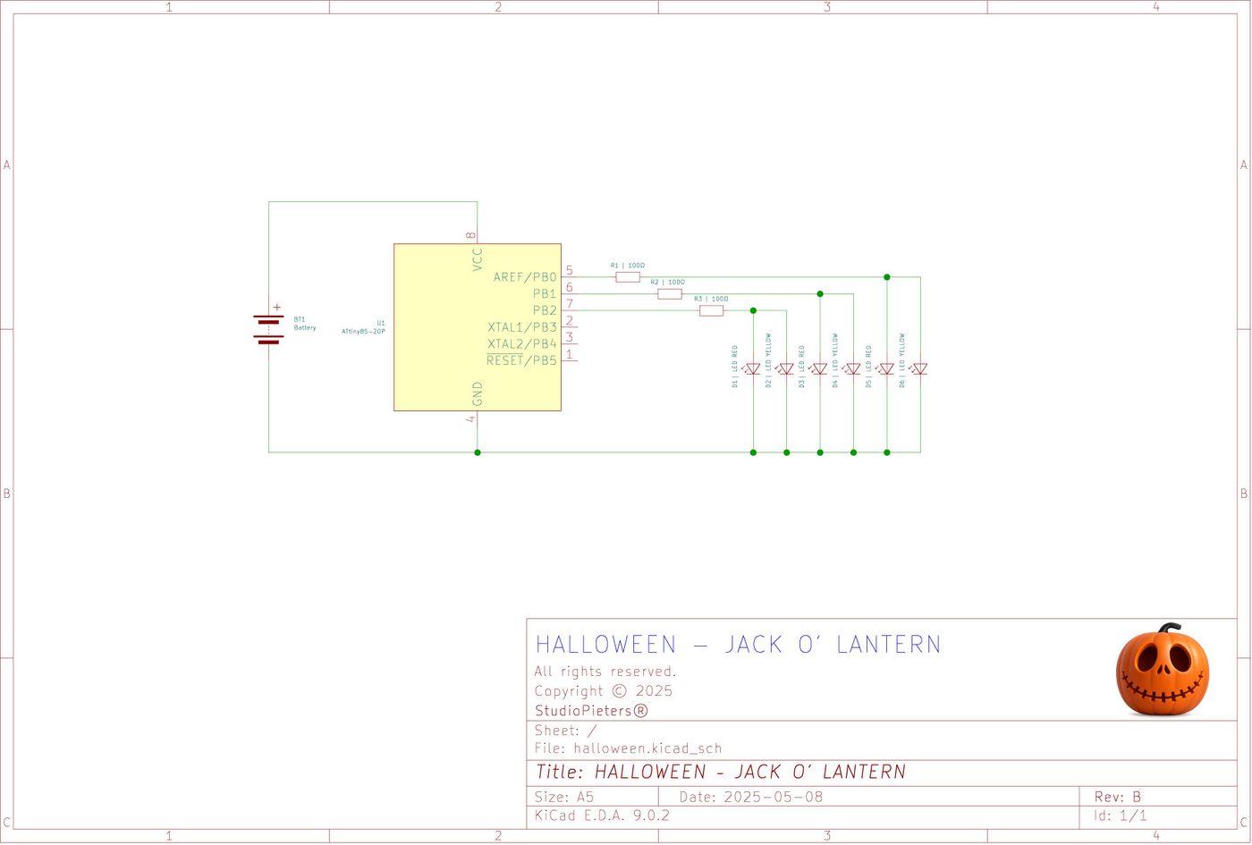
We’ll simulate a realistic flickering flame using PWM on pins 0 and 1, and use digitalWrite on pin 2 to simulate a blinking flame for extra brightness.
I wanted this circuit brighter than the typical projects, so I used 6 LED's:
- 3 pairs in parallel,
- powered by 3x AA batteries (4.5V),
- with 100Ω resistors (you could go even lower if needed).
If you don’t have parts lying around, here’s your BOM:
Bill of Materials
| Quantity | Component | |
|---|---|---|
| 1 | Microchip ATtiny85 | 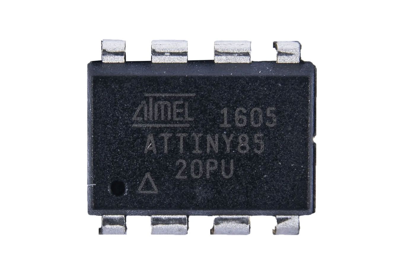 |
| 3 | 100Ω Resistors |  |
| 3 | Red 5mm LED's |  |
| 3 | Yellow 5mm LED's |  |
| 3 | AA Batteries |  |
| 1 | AA Battery Holder |  |
| 1 | Universal PCB (2x8 cm) | 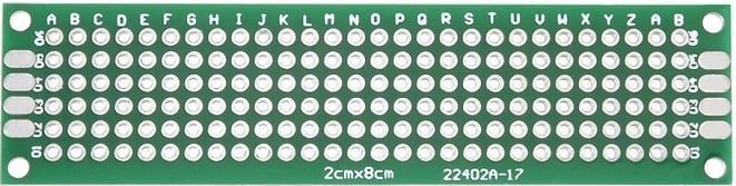 |
Circuit Diagram
Here’s the basic schematic for this flickering candle circuit:
Six LED's (three pairs) simulate a flame effect using PWM and random flickering.

Code
How to program an ATTiny you can ready here:
View the full source code
/*
   Halloween - Jack O' Lantern

   Copyright 2025 Achim Pieters | StudioPieters®

   Permission is hereby granted, free of charge, to any person obtaining a copy
   of this software and associated documentation files (the "Software"), to deal
   in the Software without restriction, including without limitation the rights
   to use, copy, modify, merge, publish, distribute, sublicense, and/or sell
   copies of the Software, and to permit persons to whom the Software is
   furnished to do so, subject to the following conditions:

   The above copyright notice and this permission notice shall be included in all
   copies or substantial portions of the Software.

   THE SOFTWARE IS PROVIDED "AS IS", WITHOUT WARRANTY OF ANY KIND, EXPRESS OR
   IMPLIED, INCLUDING BUT NOT LIMITED TO THE WARRANTIES OF MERCHANTABILITY,
   FITNESS FOR A PARTICULAR PURPOSE AND NON INFRINGEMENT. IN NO EVENT SHALL THE
   AUTHORS OR COPYRIGHT HOLDERS BE LIABLE FOR ANY CLAIM, DAMAGES OR OTHER LIABILITY,
   WHETHER IN AN ACTION OF CONTRACT, TORT OR OTHERWISE, ARISING FROM, OUT OF OR IN
   CONNECTION WITH THE SOFTWARE OR THE USE OR OTHER DEALINGS IN THE SOFTWARE.

*/

int ledPin1 = 0;
int ledPin2 = 1;
int ledPin3 = 2;

void setup() {
  pinMode(ledPin1, OUTPUT);
  pinMode(ledPin2, OUTPUT);
  pinMode(ledPin3, OUTPUT);
}

void loop() {
  // analogWrite(ledPin1, random(50)+200);
  // analogWrite(ledPin2, random(80)+170);
  analogWrite(ledPin1, random(250));
  analogWrite(ledPin2, random(250));

  digitalWrite(ledPin3, HIGH);
  delay(random(200));
  digitalWrite(ledPin3, LOW);
}Testing the Code
Once programmed, insert the ATTiny85 into your breadboard or solder it onto your prototype board. Connect your LED's in 3 parallel pairs, hook up the resistors, and power the circuit using 3 AA batteries.
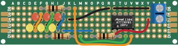
Once powered on, you’ll see:
- A realistic flame flicker on two LED's (PWM),
- One blinking LED pair for added sparkle.
It's spooky, re-usable, and perfectly safe!
FREE Stencil Download
Want to make your own Jack O’ Lantern face? Download one of these stencil's to complete the Halloween experience!


ALL FREE TO DOWNLOAD!
Final Thoughts
This project is a fun, safe, and creative way to enhance your Halloween decorations. With only a handful of cheap components, you can ditch the candles and enjoy a flickering pumpkin every year. Plus, the ATTiny85 makes it a great beginner microcontroller project for kids and adults alike.
Happy Halloween!