By integrating prints with screws, nuts, fasteners, and pins, we create a robust system for constructing mechanisms with capabilities surpassing what can be achieved through standalone 3D printing. Today, I want to share insights into one of my preferred functional 3D-printing methodologies: the incorporation of heat-set inserts. Having manually embedded these inserts into plastic components for numerous years, I believe many guides overlook crucial procedural details essential for achieving consistent outcomes.

Make no mistake; there are already several insert guides available. (In fact, I recommend consulting these resources initially for a solid starting point.) Nevertheless, throughout the years, I’ve introduced my own final touch, a technique I’ve coined the “Plate-Press Technique.” This uncomplicated yet effective approach has significantly enhanced the consistency of my results. Join me below as I address the gaps in knowledge (both figurative and literal) to provide you with a comprehensive understanding of a technique that guarantees perfectly-seated inserts every time you embark on your projects in the lab.

Heat-Set Insert “Theory”
Every type of 3D-printed material is essentially a thermoplastic, making them universally compatible with heat-set inserts. It’s as if these inserts were tailor-made for the materials, although, in reality, they weren’t designed with each other in mind. Fortunately, the widespread use of injection-molding plastic has turned these inserts into readily available components.
The functionality of heat-set inserts lies in their ability to soften the surrounding material during installation. Once in place, removing the heat source causes the molten plastic to solidify around the inserts’ knurled feature, securing them firmly. To understand this process in terms of heat transfer, it’s crucial to note that the installation holes are intentionally smaller than the inserts (undersized). Therefore, manual force alone cannot install the inserts. Instead, the insert is heated, and the heat is conducted into the surrounding material, causing the hole to deform and accommodate the larger insert.
Consider the time aspect: as the insertion tool transfers heat, it moves through the insert via surface area contact and eventually dissipates outward into the 3D-printed part. The longer the insertion process takes, the more time the heat has to travel into the part, potentially causing deformation in the surrounding areas. While large-scale manufacturing relies on machines for this process, manual installation requires careful timing. Additionally, it’s important to remember that during insert installation, molten plastic is displaced to make room for the heat-set insert. This displaced plastic typically accumulates at the bottom of the insert.
There’s a Tool for That
Our tools don’t have to break the bank. I utilize an “installation tip” in conjunction with an affordable 40W soldering iron from Amazon, sans temperature control. Unlike conventional soldering iron tips, these “installation tips” lack a taper. The absence of a taper simplifies the removal of the tip once the insert is in place.
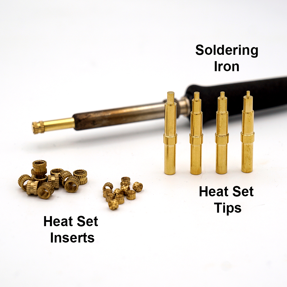
For soldering iron inserts, check McMaster-Carr (pn: 92160a115) or Tindie. While I use the McMaster-Carr variant for 4-40 and M2.5 inserts, it also works seamlessly with M3, M4, and M5 inserts!

I strongly advise against using a standard soldering iron tip due to a crucial reason. Many of these tips have a tapered design. If a tapered soldering iron tip is employed, there’s a risk of it getting stuck in the insert. Remember, metal expands when heated and contracts when cooled. As we insert the metal into the printed part, heat is transferred from the insert to the part, causing the heated insert to cool and contract around the iron tip. Consequently, attempting to pull out the iron tip may result in the insert coming with it – a situation likened to a Chinese finger trap.
While this issue didn’t occur frequently for me when using a standard soldering iron tip in the past, experiencing a 1-out-of-5 failure rate prompted me to invest an extra $10 in acquiring the appropriate tip.
Lastly, my final tool in this process is a small square of thin sheet metal, approximately 150x150mm (6″x6″). This sheet serves as a “flat” reference, a concept I’ll delve into later in the process.
Designing for Inserts:
When determining the appropriate hole size for inserts, it’s advisable to adhere to the dimensional information provided in the insert datasheets. Below are links to some of my preferred inserts along with their recommended hole sizes for quick reference:
- UD-43030 short M3x0.5 insert (relevant dimensions, vendor)
- 94180A331 M3x0.5 tapered insert (relevant dimensions and vendor)
- 93365A120 #4-40 tapered insert (relevant dimensions and vendor)
To account for displaced material, I recommend increasing the hole depth by approximately 50% of the insert length. This adjustment ensures that any displaced plastic has sufficient space to avoid filling up the insert cavity.
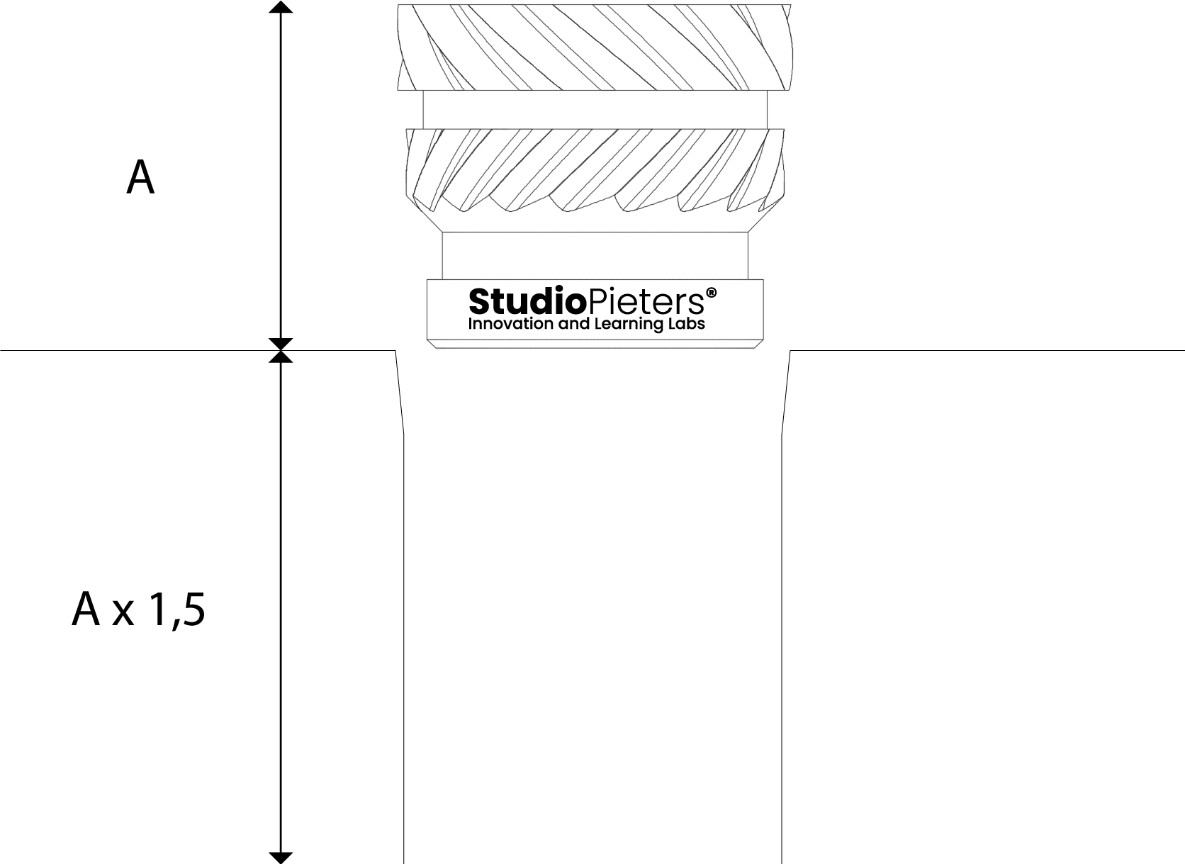
Another consideration is to incorporate a small taper to the hole feature. This feature allows inserts to self-seat into the hole before installation with heat. While not mandatory, adding this tapered feature or opting for slightly more expensive tapered inserts can enhance the insertion process.
Slicer Settings:
To accommodate displaced material, I suggest augmenting the depth of the hole by around 50% of the insert length. This modification ensures ample space for any displaced plastic, preventing it from occupying the insert cavity.
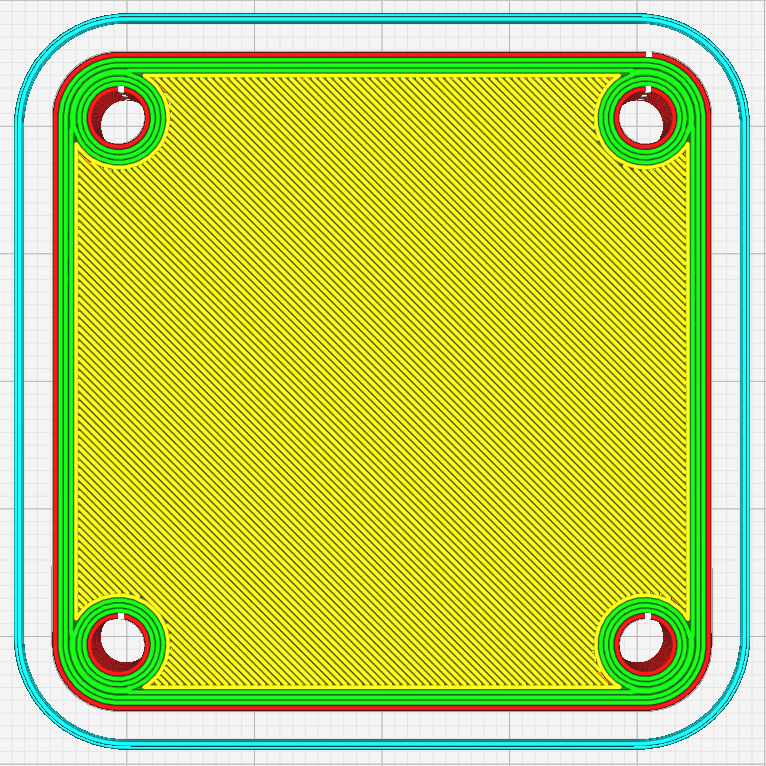
Additionally, it’s advisable to introduce a slight taper to the hole feature. This modification enables inserts to naturally align with the hole during installation with heat. While not obligatory, integrating this tapered feature or opting for slightly pricier tapered inserts can improve the overall insertion process.
The Installation Process and the Plate-Press Technique:
Now that we’ve covered the design and preparation of parts for inserts, let’s delve into the installation procedure.

Begin by ensuring that your soldering iron has reached its designated temperature before using it for insert installation. Attempting to install an insert while the iron is still heating up prolongs the process, allowing excess heat to diffuse into the part, potentially causing warping.
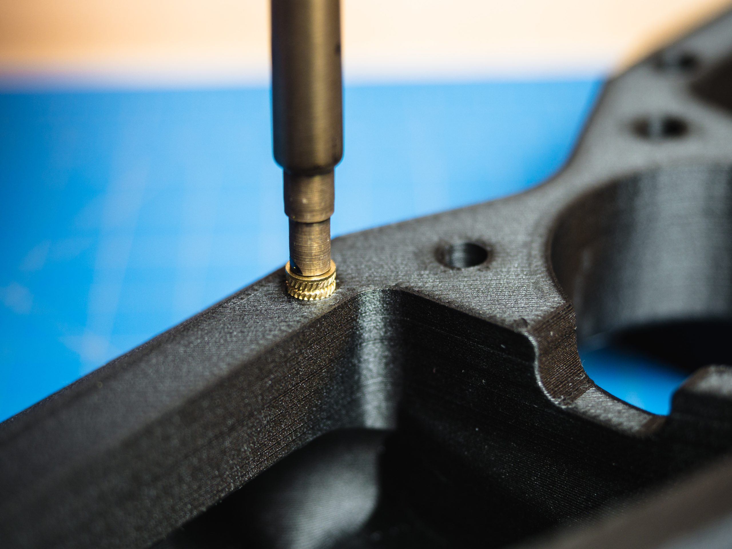
Once the insert is positioned in the hole, apply heat to it. Allow the soldering iron’s weight to exert the gentle force required to push the insert into place, with gravity assisting in the process. This step typically takes around 10–15 seconds. Continue applying heat until the insert is approximately 90% seated in the part.
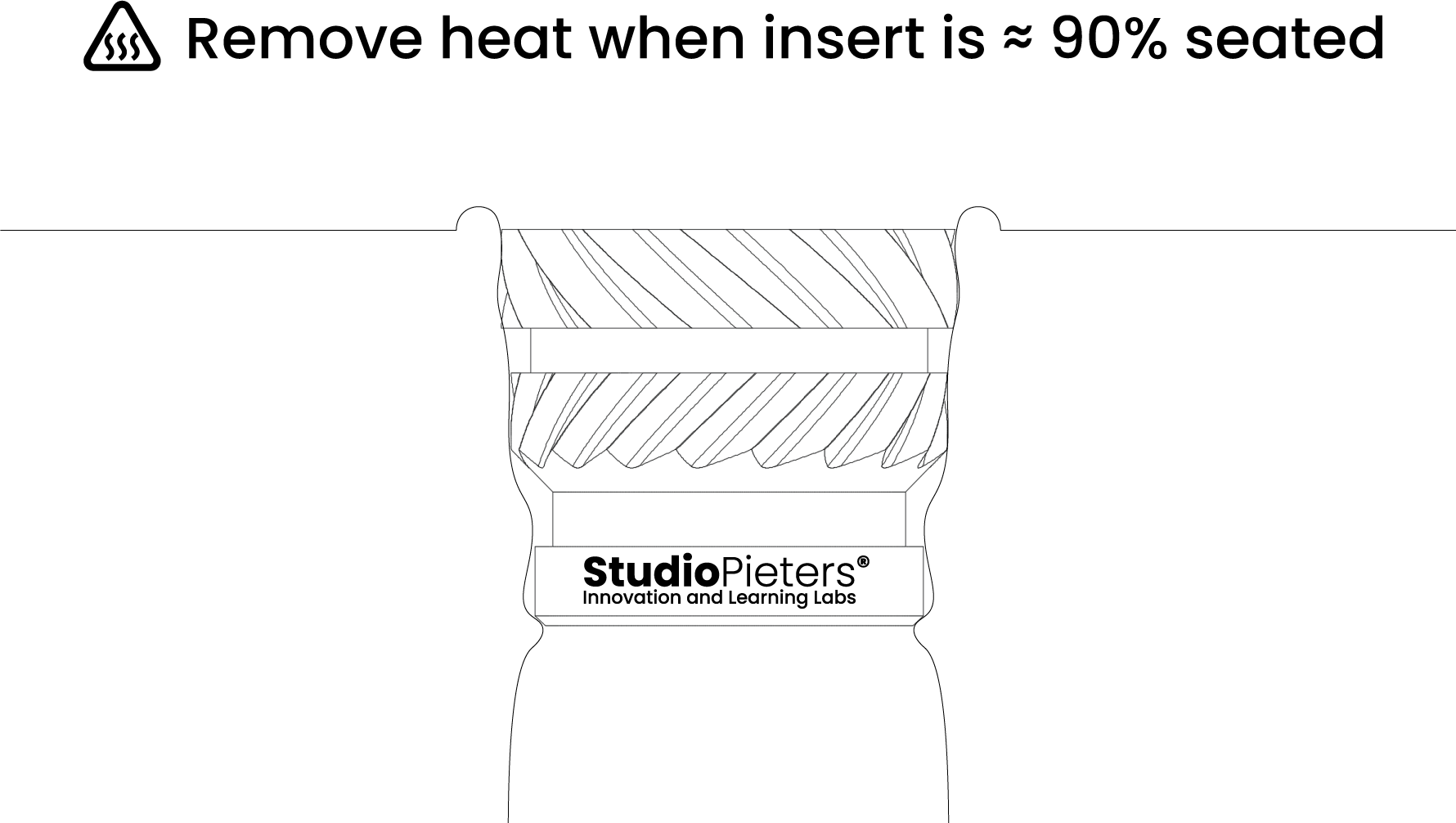
Now, deviate from the conventional approach. When the insert is about 90% in place, remove the iron, swiftly flip the part onto a flat, heat-resistant surface, and gently press the part down until it sits flush with the material. For this step, a small piece of sheet metal can be used. Wait for about 6-10 seconds to let the part cool, completing the process. This unconventional technique, known as the plate-press maneuver, serves two critical purposes.
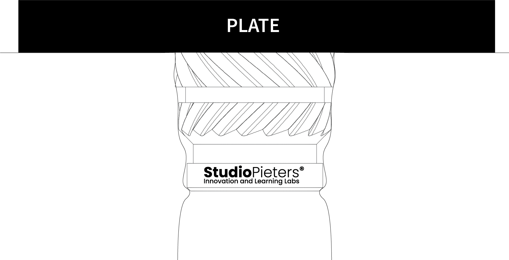
Firstly, it ensures that the insert is both vertical and completely flush with the top of the printed part. Secondly, it flattens any protruding material that may have developed during the insert installation process.

Results
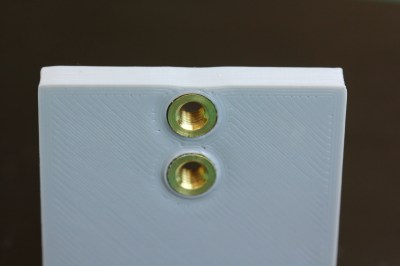
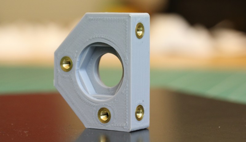
If everything went smoothly, you should now have an insert that seamlessly blends with the part surface. In the accompanying image, I employed the iron to partially seat these components and then utilized the plate-press technique to cool them flush.
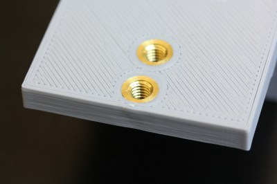
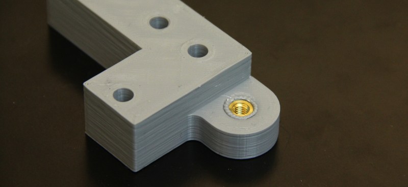
In the subsequent example, this insert was placed without employing the plate-press technique. Take note of the undesirable “bulge” of excess material that accumulates around the insert. This is precisely the bulge that can be eliminated by using the plate-press technique in the final step.
Conclusion:
I speculate that adjusting both the iron temperature and insertion speed might mitigate or eliminate this bulging effect through consistent practice in various conditions. However, the perceived need for such practice underscores the value of the plate-press technique. In simple terms, this technique provides consistent results without requiring precision at the level of a robot. We essentially “smoosh” the insert into its final position and finish the task effortlessly. While admittedly not the method employed in mass production within the industry, it proves remarkably consistent—a kind of hack.

And there you have it! I trust this guide aids you in achieving flawlessly flush inserts every time, minimizing manual effort.
References:
https://markforged.com/blog/heat-set-inserts/
https://www.ptonline.com/articles/four-ways-to-tackle-threaded-inserts-for-plastics
https://hackaday.com/2019/02/28/threading-3d-printed-parts-how-to-use-heat-set-inserts/