
HomeKit
ESP8266 HomeKit Garage Door Opener
A HomeKit garage door opener on an ESP8266: a relay pulses the opener input and a reed sensor with a magnet on the door reports open or closed. A low-voltage test setup, built from source.
- ESP8266
- HomeKit
- Safety notes
- 4 min read
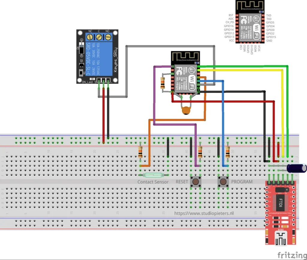
A HomeKit garage door opener on an ESP8266. It shows up in the Home app as a garage door, opens and closes it by pulsing a relay that is wired to the input of the opener, and reads a reed sensor with a magnet on the door to know whether the door is open or closed.
This is a low-voltage test setup, and part of learning: the author got more skilled at programming with this project and understood better how HomeKit works.
Read this first
When you add the accessory to the Home app, HomeKit sends an Identify request, and this firmware answers it by pulsing the relay three times. That can start the garage door, so keep people and objects clear of the door while you add the accessory.
The relay is wired to the input of the garage door opener, in the test setup on low voltage. Do not connect mains voltage to the relay unless you know how to work on it safely.
What it does
| Feature | Details |
|---|---|
| HomeKit service | Garage Door Opener, with current door state, target door state and obstruction detected. Obstruction detection always reports no obstruction |
| Opening and closing | A request pulses the relay for 0.4 seconds, like pressing the button of the opener |
| Door position | A reed sensor with a magnet on the door reports whether the door is open or closed |
| Travel time | After a request the state shows opening or closing for 22 seconds, then the sensor is read |
| No cloud | Control stays on your own network |
Hardware
| Component | Notes |
|---|---|
| ESP8266 module | An Ai-Thinker ESP8266 module of the ESP-12 type. See the ESP8266 pinout |
| 1-channel relay module | A Keyes SRD-05VDC-SL-C module, wired to the input of the garage door opener |
| Reed contact and magnet | Shown as the contact sensor in the diagram, with the magnet on the door |
| 2 push buttons | RESET and PROGRAM |
| USB-serial (FTDI) adapter | For flashing and for power in this test setup. Set it to 3.3 V logic |
| 470 µF capacitor | Across the supply, needed for stable operation when powering from the FTDI adapter |
| Resistors | Pull-ups, as drawn |
In this test setup the module is powered from the FTDI adapter, which is not recommended for long-term use.
Wiring and pins
The Fritzing diagram at the top of this page shows the build on a breadboard, with the pinout of the module in the corner. The pins are set in the Makefile of the project:
| Function | ESP8266 pin |
|---|---|
| Relay | GPIO2 |
| Reed sensor | GPIO4 |
The firmware switches the relay by pulling its pin low. The reed sensor input uses the internal pull-up, and every change of the input triggers an interrupt. Use an FTDI adapter set to 3.3 V, because a 5 V adapter can damage the module.
How the door state works
The firmware reads the reed contact as follows: when the contact is closed, the door is reported as open, and when the contact is open, the door is reported as closed. The magnet on the door decides which of the two happens where, so check the state in the Home app after you mount the sensor.
| Situation | What the firmware does |
|---|---|
| Request to open while closed | Pulses the relay, reports opening, and after 22 seconds reads the sensor |
| Request to close while open | Pulses the relay, reports closing, and after 22 seconds reads the sensor |
| Request equal to the current state | Ignored |
| Request while opening or closing | Ignored |
| Sensor changes while opening or closing | Ignored until the 22 seconds are over |
Build from source
This repository has no release with a ready-made binary, so you compile the firmware yourself. It builds with ESP-Open-RTOS and the esp-homekit library by Maxim Kulkin. The Makefile expects the wifi_config, cJSON, wolfssl and homekit components in the folder layout of that project, and the http-parser and dhcpserver extras of the SDK.
| File | What it is |
|---|---|
| garage/garage.c | The accessory, the door state logic and the relay toggle |
| garage/contact_sensor.c | The reed sensor input with its interrupt |
| garage/relay_actor.c | The relay output |
| garage/button_sensor.c | A button input |
| garage/wemos.h | GPIO names as printed on WEMOS D1 style boards |
| garage/garage.c2 | An alternative version of the source |
| garage/Makefile | Build settings: REED_PIN 4, RELAY_PIN 2, FLASH_SIZE 32, and a serial monitor at 9600 baud |
The HomeKit setup code is set in garage.c. Change it to your own before you use the device for real.
Good to know
- This is a low-voltage test setup and not a finished product.
- The HomeKit Accessory Protocol specification the firmware follows is the non-commercial version, for accessories you build yourself and do not distribute or sell.
- The repository is under the MIT licence.
Everything is in the ESP8266-HomeKit-Garage-Door repository on GitHub.
Related
 HomeKit
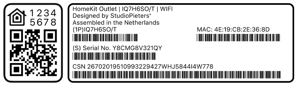
Guide to ESP32 HomeKit QR Codes
An elegant tool to generate a full HomeKit pairing label, complete with a scannable QR code, setup code, MAC address and barcoded serials, so provisioning an ESP32 HomeKit accessory looks as polished as a real Apple-certified product.
Read more
HomeKit
Guide to ESP32 HomeKit QR Codes
An elegant tool to generate a full HomeKit pairing label, complete with a scannable QR code, setup code, MAC address and barcoded serials, so provisioning an ESP32 HomeKit accessory looks as polished as a real Apple-certified product.
Read more
 HomeKit
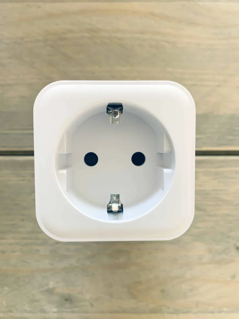
LSC Smart Plug with an ESP8285 as a HomeKit Outlet
The LSC Smart Connect plug from Action, flashed through its TYWE2S module with an FTDI adapter, as an Apple HomeKit outlet with over-the-air updates.
Read more
HomeKit
LSC Smart Plug with an ESP8285 as a HomeKit Outlet
The LSC Smart Connect plug from Action, flashed through its TYWE2S module with an FTDI adapter, as an Apple HomeKit outlet with over-the-air updates.
Read more
 HomeKit
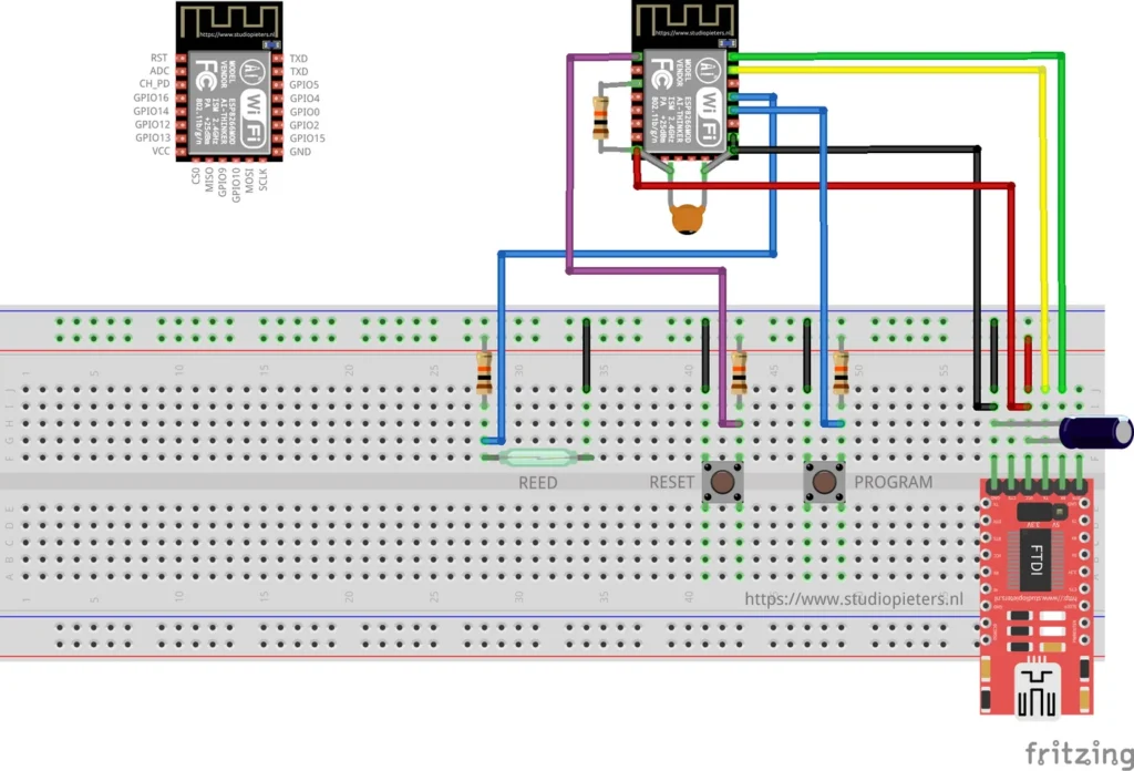
ESP8266 HomeKit Reed Contact Sensor
A HomeKit contact sensor on an ESP8266 with a reed contact and a magnet, for a door, window, garage door or blinds. A test setup from 2019.
Read more
HomeKit
ESP8266 HomeKit Reed Contact Sensor
A HomeKit contact sensor on an ESP8266 with a reed contact and a magnet, for a door, window, garage door or blinds. A test setup from 2019.
Read more
More HomeKit
Keep building.
Switches, sensors, plugs and blinds: more accessories that you build yourself and add to the Home app.
All HomeKit