Since Espressif Systems arrived in our collective consciousness, they have expanded their range from the ESP8266 to the ESP32, and going beyond the original WROOM and WROVER modules to a range of further ESP32 products. There’s a single-core variant and one that packs a RISC-V core in place of the Tensilica one, and now they’ve revealed their latest product. The ESP32-S3 WROOM takes the ESP to a new level, packing as it does more I/O, onboard USB, and an updated version of the two Tensilica cores alongside Bluetooth version 5. It’s still an ESP32, but one that’s more useful, and it’s worth a closer look because we expect it to figure in quite a few projects.
ESP32-S3 WROOM Peripherals
The ESP32-S3 peripherals include:
- 20 Analogue to Digital Converter (ADC) channels
- 4 SPI interfaces
- 2 UART interfaces
- 2 I2C interfaces
- 8 PWM (LEDC) output channels
- 2 Digital to Analogue Converters (DAC)
- 1 I2S interfaces
- 14 Capacitive sensing GPIO’s
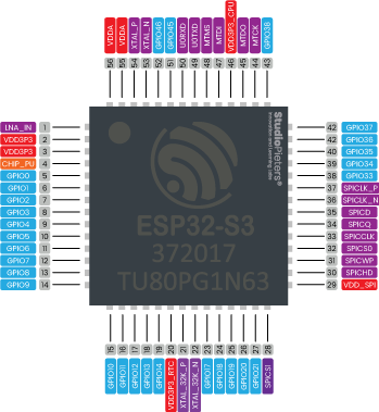
The ADC (analogue to digital converter) and DAC (digital to analogue converter) features are assigned to specific static pins. However, you can decide which pins are UART, I2C, SPI, PWM, etc. – you just need to assign them in the code. This is possible due to the ESP32-S3 chip’s multiplexing feature.

Additionally, there are pins with specific features that make them suitable or not for a particular project. The following table shows what pins are best to use as inputs, outputs and which ones you need to be cautious.

The pins highlighted in green are OK to use. The ones highlighted in yellow are OK to use, but you need to pay attention because they may have an unexpected behaviour, mainly at boot. The pins highlighted in red are not recommended to use as inputs or outputs.
| GPIO | Input | Output | Notes |
| 0 | — | — | RTC_GPIO0, GPIO0 |
| 1 | OK | OK | RTC_GPIO1, GPIO1, TOUCH1, ADC1_CH0 |
| 2 | OK | OK | RTC_GPIO2, GPIO2, TOUCH2, ADC1_CH1 |
| 3 | OK | OK | RTC_GPIO3, GPIO3, TOUCH3, ADC1_CH2 |
| 4 | OK | OK | RTC_GPIO4, GPIO4, TOUCH4, ADC1_CH3 |
| 5 | OK | OK | RTC_GPIO5, GPIO5, TOUCH5, ADC1_CH4 |
| 6 | OK | OK | RTC_GPIO6, GPIO6, TOUCH6, ADC1_CH5 |
| 7 | OK | OK | RTC_GPIO7, GPIO7, TOUCH7, ADC1_CH6 |
| 8 | OK | OK | RTC_GPIO8, GPIO8, TOUCH8, ADC1_CH7 |
| 9 | OK | OK | RTC_GPIO9, GPIO9, TOUCH9, ADC1_CH8, FSPIHD |
| 10 | OK | OK | RTC_GPIO10, GPIO10, TOUCH10, ADC1_CH9, FSPICS0, FSPIIO4 |
| 11 | OK | OK | RTC_GPIO11, GPIO11, TOUCH11, ADC2_CH0, FSPID, FSPIIO5 |
| 12 | OK | OK | RTC_GPIO12, GPIO12, TOUCH12, ADC2_CH1, FSPICLK, FSPIIO6 |
| 13 | OK | OK | RTC_GPIO13, GPIO13, TOUCH13, ADC2_CH2, FSPIQ, FSPIIO7 |
| 14 | OK | OK | RTC_GPIO14, GPIO14, TOUCH14, ADC2_CH3, FSPIWP, FSPIDQS |
| 15 | OK | OK | RTC_GPIO15, GPIO15, U0RTS, ADC2_CH4, XTAL_32K_P |
| 16 | OK | OK | RTC_GPIO16, GPIO16, U0CTS, ADC2_CH5, XTAL_32K_N |
| 17 | OK | OK | RTC_GPIO17, GPIO17, U1TXD, ADC2_CH6, DAC_1 |
| 18 | OK | OK | RTC_GPIO18, GPIO18, U1RXD, ADC2_CH7, DAC_2, CLK_OUT3 |
| 19 | OK | OK | RTC_GPIO19, GPIO19, U1RTS, ADC2_CH8, CLK_OUT2, USB_D- |
| 20 | OK | OK | RTC_GPIO20, GPIO20, U1CTS, ADC2_CH9, CLK_OUT1, USB_D+ |
| 21 | OK | OK | RTC_GPIO21, GPIO21 |
| 22 | OK | OK | |
| 23 | OK | OK | |
| 24 | OK | OK | |
| 25 | OK | OK | |
| 26 | — | — | SPICS1, GPIO26 |
| 27 | — | — | SPIHD, GPIO27 |
| 28 | — | — | SPIWP, GPIO28 |
| 29 | — | — | SPICS0, GPIO29put only |
| 30 | — | — | SPICLK, GPIO30 |
| 31 | — | — | SPIQ, GPIO31 |
| 32 | — | — | SPID, GPIO32 |
| 33 | OK | OK | SPIIO4, GPIO33, FSPIHD |
| 34 | OK | OK | SPIIO5, GPIO34, FSPICS0 |
| 35 | OK | OK | SPIIO6, GPIO35, FSPID |
| 36 | OK | OK | SPIIO7, GPIO36, FSPICLK |
| 37 | OK | OK | SPIDQS, GPIO37, FSPIQ |
| 38 | OK | OK | GPIO38, FSPIWP |
| 39 | OK | OK | MTCK, GPIO39, CLK_OUT3 |
| 40 | OK | OK | MTDO, GPIO40, CLK_OUT2 |
| 41 | OK | OK | MTDI, GPIO41, CLK_OUT1 |
| 42 | OK | OK | MTMS, GPIO42 |
| 43 | OK | OK | U0TXD, GPIO43, CLK_OUT1 |
| 44 | OK | OK | U0RXD, GPIO44, CLK_OUT2 |
| 45 | — | — | GPIO45 |
| 46 | OK | — | GPIO46 |
Note
- Strapping pin: GPIO0, GPIO45 and GPIO46 are strapping pins.
- SPI0/1: GPIO26-32 are usually used for SPI flash and PSRAM and not recommended for other uses.
- JTAG: GPIO39-42 are typically used for inline debug.
- GPI: GPIO46 is fixed to pull-down and is input only.

Input only pins
GPIO 46 Is an GPI’s – input only pin. These pins don’t have internal pull-up or pull-down resistors. They can’t be used as outputs, so use these pins only as inputs:
- GPIO 46
SPI flash integrated on the ESP32-S3
GPIO 26 – GPIO 32 are exposed in some ESP32-S3 development boards. However, these pins are connected to the integrated SPI flash on the ESP32-S3 WROOM chip and are not recommended for other uses. So, don’t use these pins in your projects:
- GPIO 26
- GPIO 27
- GPIO 28
- GPIO 29
- GPIO 30
- GPIO 31
- GPIO 32
Capacitive touch GPIO’s
The ESP32-S3 has 14 internal capacitive touch sensors. These can sense variations in anything that holds an electrical charge, like the human skin. So they can detect variations induced when touching the GPIO’s with a finger. These pins can be easily integrated into capacitive pads and replace mechanical buttons. The capacitive touch pins can also be used to wake up the ESP32-S3 from deep sleep.
Those internal touch sensors are connected to these GPIO’s:
- Touch1 (GPIO 1)
- Touch2 (GPIO 2)
- Touch3 (GPIO 3)
- Touch4 (GPIO 4)
- Touch5 (GPIO 5)
- Touch6 (GPIO 6)
- Touch7 (GPIO 7)
- Touch8 (GPIO 8)
- Touch9 (GPIO 9)
- Touch10 (GPIO 10)
- Touch11 (GPIO 11)
- Touch12 (GPIO 12)
- Touch13 (GPIO 13)
- Touch14 (GPIO 14)

Analog to Digital Converter (ADC)
The ESP32-S3 has 2 SAR (Successive Approximation Register) ADC’s, supporting a total of 20 measurement channels (analog enabled pins). These are the GPIO’s that can be used as ADC and respective channels:
- ADC1_CH0 (GPIO 1)
- ADC1_CH1 (GPIO 2)
- ADC1_CH2 (GPIO 3)
- ADC1_CH3 (GPIO 4)
- ADC1_CH4 (GPIO 5)
- ADC1_CH5 (GPIO 6)
- ADC1_CH6 (GPIO7)
- ADC1_CH7(GPIO8)
- ADC1_CH8 (GPIO 9)
- ADC1_CH9 (GPIO 10)
- ADC2_CH0 (GPIO 11)
- ADC2_CH1 (GPIO 12)
- ADC2_CH2 (GPIO 13)
- ADC2_CH3 (GPIO 14)
- ADC2_CH4 (GPIO 15)
- ADC2_CH5 (GPIO 16)
- ADC2_CH6 (GPIO 17)
- ADC2_CH7 (GPIO 18)
- ADC2_CH8 (GPIO 19)
- ADC2_CH9 (GPIO 20)
ADC Attenuation
Vref is the reference voltage used internally by ESP32-S2 ADC’s for measuring the input voltage. The ESP32-S2 ADC’s can measure analog voltages from 0 V to Vref. Among different chips, the Vref varies, the median is 1.1 V. In order to convert voltages larger than Vref, input voltages can be attenuated before being input to the ADC’s. There are 4 available attenuation options, the higher the attenuation is, the higher the measurable input voltage could be.
ADC Limitations
Since the ADC2 module is also used by the Wi-Fi, reading operation of adc2_get_raw() may fail between esp_wifi_start() and esp_wifi_stop(). Use the return code to see whether the reading is successful.
Digital to Analog Converter (DAC)
There are 2 × 8 bits DAC channels on the ESP32-S2 to convert digital signals into analog voltage signal outputs. These are the DAC channels:
- DAC1 (GPIO17)
- DAC2 (GPIO18)
RTC GPIO’s
There is RTC GPIO support on the ESP32-S2. The GPIO’s routed to the RTC low-power subsystem can be used when the ESP32-S2 is in deep sleep. These RTC GPIO’s can be used to wake up the ESP32-S2 from deep sleep when the Ultra Low Power (ULP) coprocessor is running. The following GPIO’s can be used as an external wake-up source.
- RTC_GPIO0 (GPIO0) (Strapping pin)
- RTC_GPIO1 (GPIO1)
- RTC_GPIO2 (GPIO2)
- RTC_GPIO3 (GPIO3)
- RTC_GPIO4 (GPIO4)
- RTC_GPIO5 (GPIO5)
- RTC_GPIO6 (GPIO6)
- RTC_GPIO7 (GPIO7)
- RTC_GPIO8 (GPIO8)
- RTC_GPIO9 (GPIO9)
- RTC_GPIO10 (GPIO10)
- RTC_GPIO11 (GPI11)
- RTC_GPIO12 (GPI12)
- RTC_GPIO13 (GPIO13)
- RTC_GPIO14 (GPIO14)
- RTC_GPIO15 (GPIO15)
- RTC_GPIO16 (GPIO16)
- RTC_GPIO17 (GPIO17)
- RTC_GPIO18 (GPIO18)
- RTC_GPIO19 (GPIO19)
- RTC_GPIO20 (GPIO20)
- RTC_GPIO21 (GPIO21)

PWM
The ESP32-S2 LED PWM controller has 8 independent channels that can be configured to generate PWM signals with different properties. All pins that can act as outputs can be used as PWM pins.
To set a PWM signal, you need to define these parameters in the code:
- Signal’s frequency;
- Duty cycle;
- PWM channel;
- GPIO where you want to output the signal.
I2C
The ESP32-S2 has two I2C channels and any pin can be set as SDA or SCL. When using the ESP32-S3 with the Arduino IDE, the default I2C pins are:
- GPIO 8 (SDA)
- GPIO9 (SCL)
SPI
SPI Slave driver is a program that controls ESP32-S3’s SPI peripherals while they function as slaves. ESP32-S3 integrates two general purpose SPI controllers which can be used as slave nodes driven by an off-chip SPI master. SPI2 and SPI3 have independent signal buses with the same respective names.
- GPIO 34 (CS)
- GPIO 35 (MOSI)
- GPIO 36 (SCK)
- GPIO 37 (MISO)
Interrupts
The ESP32-S3 has two cores, with 32 interrupts. Each interrupt has a certain priority level, most (but not all) interrupts are connected to the interrupt mux.
Strapping Pins
The ESP32 chip has the following strapping pins:
- GPIO 0
- GPIO 45
- GPIO46
During the chip’s system reset (power-on-reset, RTC watchdog reset, brownout reset, analog super watchdog reset, and crystal clock glitch detection reset), the latches of the strapping pins sample the voltage level as strapping bits of ”0” or ”1”, and hold these bits until the chip is powered down or shut down.
GPIO0, GPIO45 and GPIO46 are connected to the chip’s internal weak pull-up/pull-down during the chip reset. Consequently, if they are unconnected or the connected external circuit is high-impedance, the internal weak pull-up/pull-down will determine the default input level of these strapping pins.
To change the strapping bit values, users can apply the external pull-down/pull-up resistances, or use the host MCU’s GPIO’s to control the voltage level of these pins when powering on ESP32-S3. After reset, the strapping pins work as normal-function pins.
Enable (EN / CHIP_PU)
Enable (EN / CHIP_PU) is the 3.3V regulator’s enable pin. It’s pulled up, so connect to ground to disable the 3.3V regulator. This means that you can use this pin connected to a pushbutton to restart your ESP32-S3, for example.
esptool.py resets ESP32-S3 automatically by asserting DTR and RTS control lines of the USB to serial converter chip, i.e., FTDI or CP210x (for more information, see Establish Serial Connection with ESP32-S3). The DTR and RTS control lines are in turn connected to GPIO0 and CHIP_PU (EN) pins of ESP32-S3, thus changes in the voltage levels of DTR and RTS will boot ESP32-S3 into Firmware Download mode.
GPIO current drawn
The absolute maximum current drawn per GPIO is 40mA according to the “Recommended Operating Conditions” section in the ESP32-S3 datasheet.

Overview
The ESP32-S3 Microcontroller is one of the most versatile boards on the market today and that’s why we decided to focus on it in this guide. This guide displays most of its capabilities, but there are also more advanced options which we did not go into in this post.
The important thing to know when you choose a board for your project is its capabilities and limitations. It’s also important to understand the different communication protocols that the board uses. Of course, you don’t need to remember all of this information, you can always go back to this post and read the relevant information for you (this is a good time to bookmark this Blog btw).