A slow, friendly, step-by-step introduction to OTA updates trough Lifecycle Manager on the ESP32. I get quite a lot of messages and questions from people who want to “try OTA updates”, but who get stuck almost immediately. Not because they’re doing something wrong, but because most tutorials quietly assume you already understand things like:
- What OTA actually is
- What “signing firmware” means
- What a key does
- How updates are verified
- And why any of this matters in the first place
If you’re reading this and thinking:
“I want to try this… but I feel like I’m missing the basics” then you are exactly the person this guide is written for. No worries. Seriously. This guide is written for people who want to understand what they’re doing, not just copy-paste something that “somehow works”.
That means:
- You may not fully understand how OTA works
- You may not know what firmware signing really does
- You may have seen terms like “private key” and “public key” without knowing what they actually mean
- And that’s completely fine
- By the end of this guide, you will:
- Understand what OTA updates actually do
- Understand why firmware signing exists
- Build a simple but controlled OTA setup
And most importantly, understand what is happening, not just follow steps. This guide is not about building something complicated. It’s about building something controlled. We’re going to create an ESP32 that can update itself, but only accepts firmware that you have signed yourself. Nothing more, nothing less. To keep things clear, we’re going to split this into two parts.
First, we build something that controls what is allowed to run on the device. Then, we build the firmware that will actually run on it.
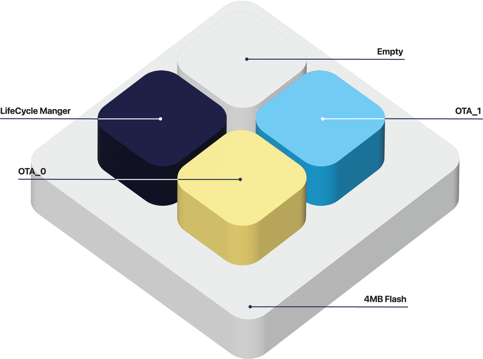
Part 1 — Lifecycle Manager (LCM)
This is the firmware that goes onto the ESP32 first. You can think of it as a small gatekeeper that sits in front of everything else. It takes care of Wi-Fi, downloading updates, and verifying whether those updates are allowed to run. In other words, it decides what the device is willing to accept.
Part 2 — your firmware
This is your own application. The Lifecycle Manager will download it, verify it, and then either install it or reject it. The important part here is that your firmware is no longer “just flashed”, it has to be accepted first.
There is really only one rule you need to remember:
- The firmware must be signed, and the Lifecycle Manager must trust that signature.
- If those two don’t match, the update will simply be rejected. That’s not an error or something going wrong, that is exactly the behavior we want.
You will come across terms like “private key”, “public key”, and “signature”. If those sound unfamiliar, don’t worry about them too much yet. For now, it’s enough to understand that one part creates a signature, and another part checks it. We’ll make that concrete step by step as we go.You will come across terms like “private key”, “public key”, and “signature”. If those sound unfamiliar, don’t worry about them too much yet. For now, it’s enough to understand that one part creates a signature, and another part checks it. We’ll make that concrete step by step as we go.
What you need
Hardware (physical things)
You need one of the following:
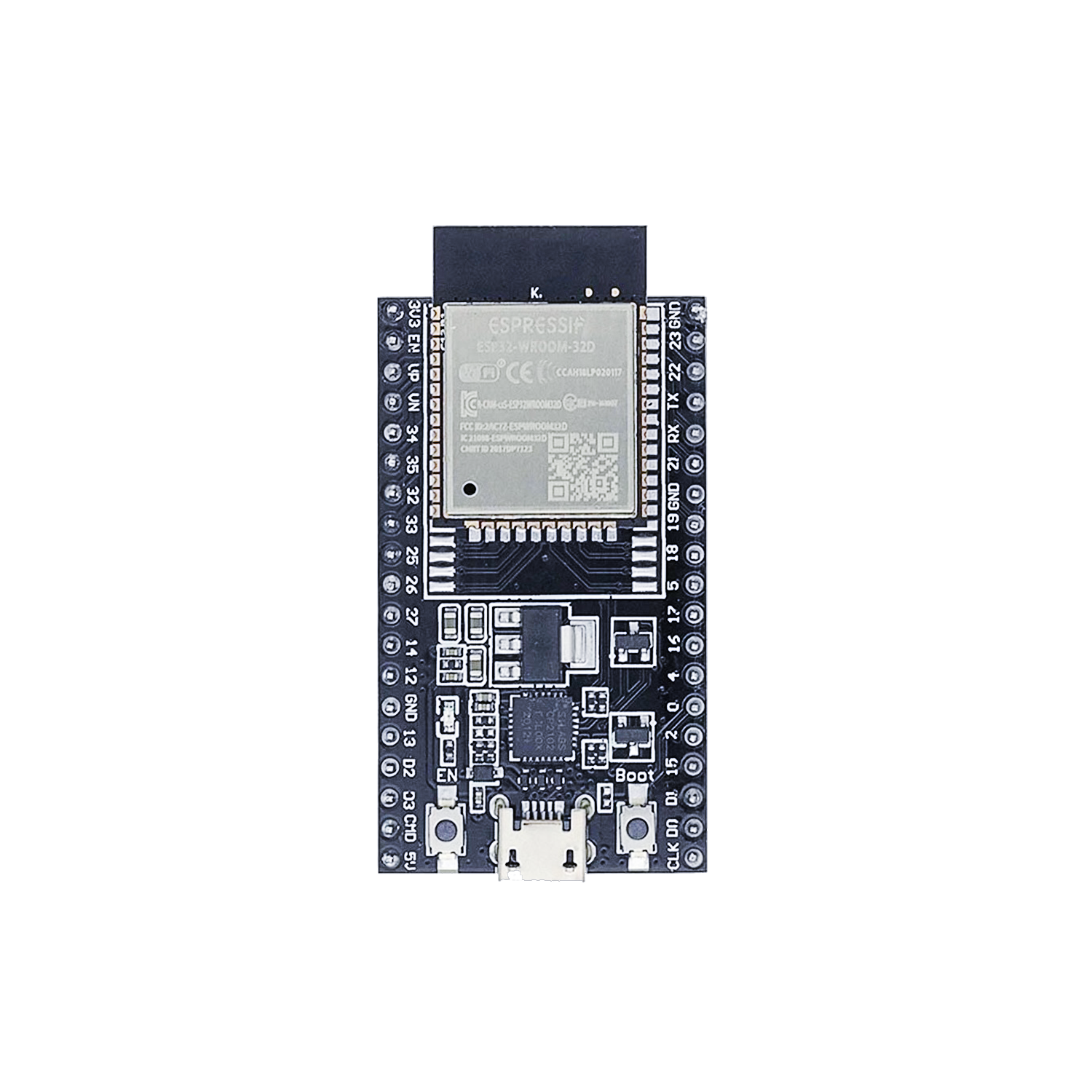
Option A (easiest – recommended)
- ESP32-WROOM-32D development board
- Has USB built in
- Has buttons
- Very beginner-friendly
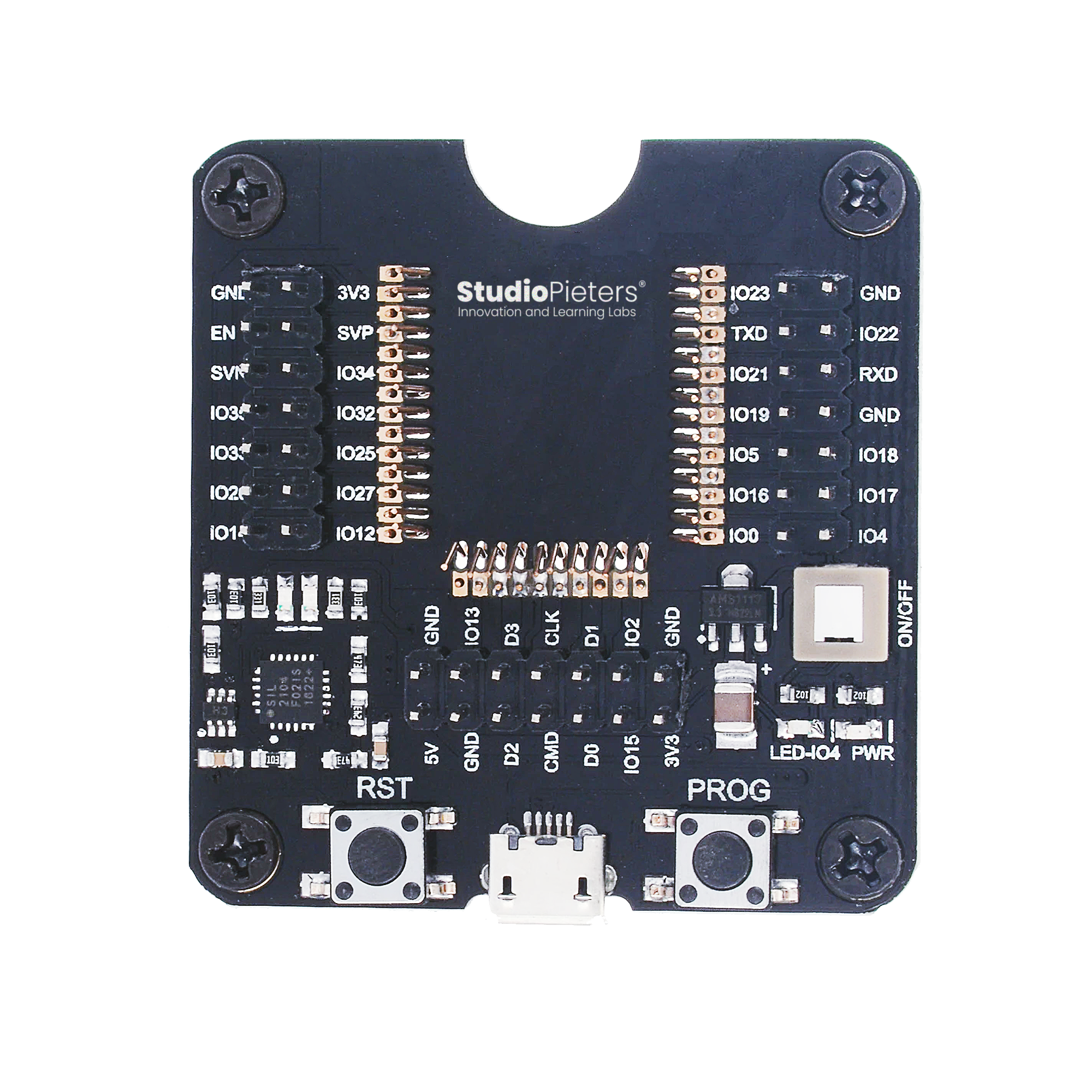
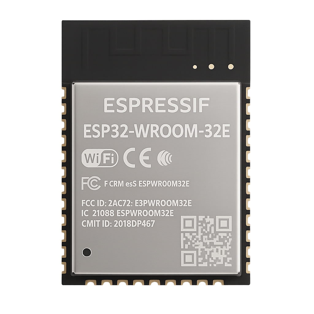
Option B (advanced, still fine)
This is my standard setup, because it gives me full control. I don’t need the flash buttons because the board manges everything form me, and all pins’s are broken out rough the pin headers. For serious development is this the best option.
- Bare ESP-WROOM-32 module
- USB programmer / baseboard
If you’re unsure → Option A is the correct choice.
You also need:
- A USB data cable (not charge-only!)
- A 2.4 GHz Wi-Fi network
- An iPhone or iPad with Apple Home
Software (things on your computer)
We will install:
- Docker Desktop
- Git
- Python 3 (for flashing)
We will not manually install ESP-IDF. Docker does that for us.
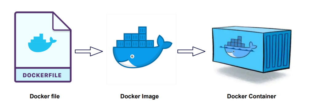
Docker (explained)
What is Docker?
Docker is like: A pre-built computer inside your computer
Inside that mini-computer:
- ESP32 tools are already installed
- Correct versions are already chosen
- Nothing breaks your real system
This avoids hours of beginner pain.
Install Docker Desktop
Download Docker Desktop
Go to: https://www.docker.com/products/docker-desktop/
Choose your OS:
- Windows
- macOS (Intel or Apple Silicon)
- Linux
Install it
- Run installer
- Accept defaults
- Finish
- Restart your computer
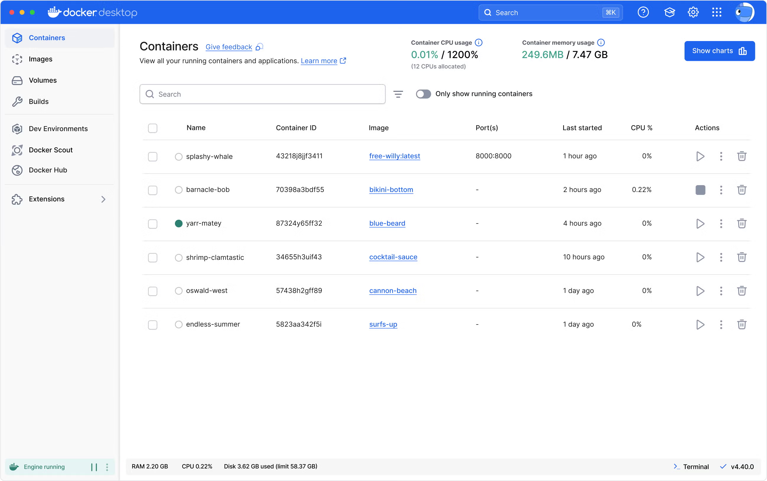
After reboot:
- Open Docker Desktop
- Make an account (it is free!) and login
- Wait until it says “Docker is running”
Check Docker works
Open a terminal:
- Windows → PowerShell
Press the “Windows” key + “R” on your keyboard to open the Run dialog. Type “powershell” into the Run dialog. Press “Ctrl” + “Shift” + “Enter” on your keyboard or press “OK” to open PowerShell with elevated privileges. - macOS → Terminal
You can open Terminal on macOS quickly using Spotlight Search (Command + Spacebar, then type “Terminal”) or by navigating through Finder to the/Applications/Utilities/folder and double-clicking the Terminal app, both methods providing the command-line interface for your Mac. - Linux → Terminal
To open the Linux Terminal, the fastest way is the shortcutCtrl + Alt + T, but you can also find it in the applications menu by searching for “Terminal,” right-click the desktop for an “Open Terminal” option, or use theAlt + F2run dialog and typegnome-terminal(orkonsole/xfce4-terminal).
Type:
docker --versionGood output looks like:
Docker version 29.x.x
Now type:
docker psYou’ll likely see an empty list. That’s perfect. Docker works If it errors then Docker Desktop is not running
Install the ESP32 development environment (ESP-IDF) using Docker
This is the step where your computer becomes an ESP32 developer machine. Take it slow — nothing scary happens here.
What is ESP-IDF (in simple words)?
ESP-IDF is the official development environment from Espressif.
It includes:
- the ESP32 compiler
- build tools
- libraries
- flashing tools
- configuration menus
Normally, installing ESP-IDF manually is:
- different per OS
- error-prone
- confusing for beginners
- very easy to break
That’s why we don’t install it directly on your computer but trough Docker.
How Docker helps here
Instead of installing ESP-IDF on your computer, we:
- download a pre-built Docker image
- that already contains ESP-IDF
- already configured
- already tested
Think of it as: “Downloading a complete ESP32 workshop in a box”
When we use this image:
- your system stays clean
- versions match the tutorials
- everyone follows the same steps
What is espressif/idf:v5.4?
This is the official ESP-IDF Docker image published by Espressif.
Let’s break it down:
- espressif → the company that makes the ESP32
- idf → ESP IoT Development Framework
- v5.4 → the exact ESP-IDF version
We lock the version so:
- examples build correctly
- HomeKit libraries stay compatible
- tutorials don’t suddenly break
Download the ESP-IDF Docker image
This step does not install anything permanently. It only downloads a file used by Docker.
Open your terminal and run:
docker pull espressif/idf:v5.4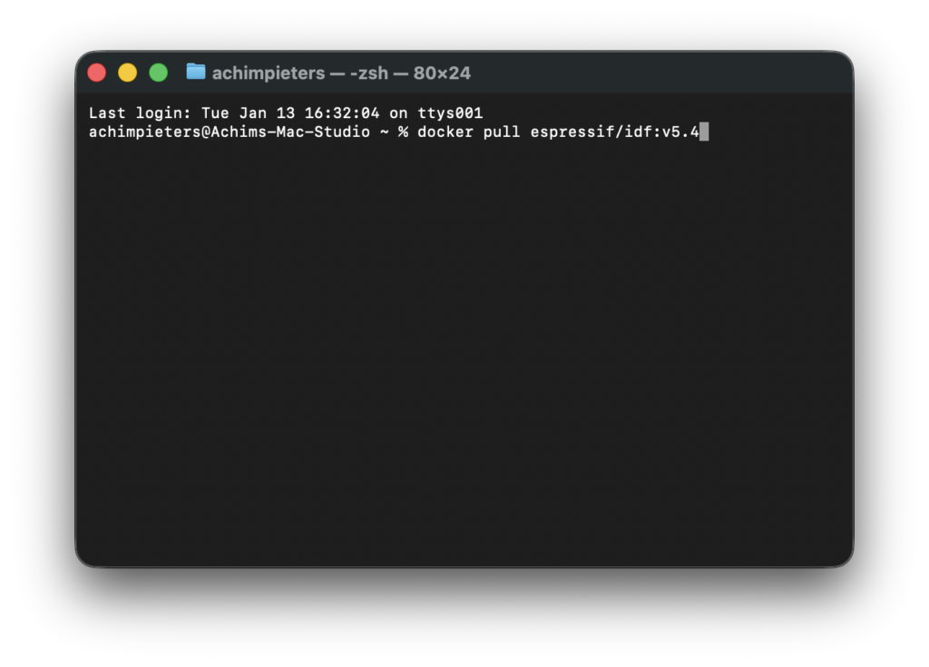
What you’ll see:
- several lines scrolling by
- Docker downloading layers
- this can take a few minutes
When it finishes without errors, ESP-IDF is now available to Docker.
How to know it worked
Run:
docker imagesYou should see something like:
REPOSITORY        TAG     IMAGE ID       SIZE
espressif/idf     v5.4    xxxxxxxx        ~4GB
That means:
- ESP-IDF v5.4 is downloaded
- Docker can use it
- You’re ready to build ESP32 firmware
Nothing is running yet — that’s normal.
Important beginner reassurance
At this point:
- You have NOT flashed anything
- You have NOT changed your ESP32
- You have NOT touched system files
You have simply:
- downloaded a development environment
- that will be used later when needed
If something goes wrong later, you can always:
docker rmi espressif/idf:v5.4No damage done.
Git (downloading code from the internet)
What is Git?
Git is a tool that:
- Downloads code from GitHub
- Keeps folders organised
- Let’s you update later
You don’t need to understand Git yet. You just need it installed.

Install Git
Download from: https://git-scm.com/downloads Install with default options.
Check if it works:
git --version
Install Python and esptool.py (needed to talk to the ESP32)
At this point you might be thinking: “Wait… didn’t we already install the ESP32 tools using Docker?” Yes — for building firmware. But flashing firmware onto a physical ESP32 still requires a small tool on your own computer. That tool is called esptool.py, and it runs using Python. Let’s break this down slowly.
Why do we need Python if we use Docker?
We use Docker for:
- compiling firmware
- managing ESP-IDF
- avoiding toolchain problems
But Docker cannot easily access USB devices on all systems.
So instead:
- we build firmware in Docker
- and flash firmware from your computer
This is intentional and beginner-friendly.
What is esptool.py?
esptool.py is:
- an official Espressif tool
- written in Python
- used to communicate with ESP32 chips over USB
- responsible for:
- erasing flash
- writing firmware
- resetting the board
You don’t need to understand Python to use it. You just run commands.
Check if Python is already installed
Open a terminal and run:
python3 --versionGood result:
Python 3.x.x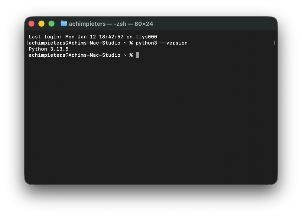
You can continue.
Bad result:
- “command not found”
- or Python 2.x
Then you need to install Python.
Install Python 3 (if needed)
Download Python from the official site: https://www.python.org/downloads/
Important options during install:
- Add Python to PATH
- Install pip (usually default)
Restart your terminal after installation.
Verify again:
python3 --versionInstall esptool.py
Now install esptool using pip:
pip3 install esptoolThis downloads and installs the flashing tool. If it does not work right away, don’t panic, see Common beginner problems below.
Verify esptool.py works
Run:
esptool.py versionGood output looks like:
esptool.py v4.x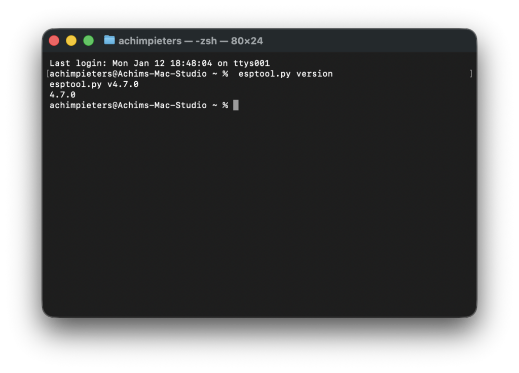
If you see a version number — success!
Common beginner problems (normal, not scary)
“pip not found”
Try:
python3 -m pip install esptoolPermission errors (macOS/Linux)
Try:
pip3 install --user esptoolWindows issues
- Re-open terminal
- Ensure Python is in PATH
- Use
python -m pip install esptool
Reassurance before moving on
At this point:
- Docker works
- ESP-IDF v5.4 exists inside Docker
- Python is installed
esptool.pyis ready
You are now fully equipped to:
- build firmware
- flash firmware
- recover your ESP32 if something goes wrong
Download the Lifecycle Manager code
git clone https://github.com/AchimPieters/esp32-lifecycle-manager.gitcd esp32-lifecycle-manager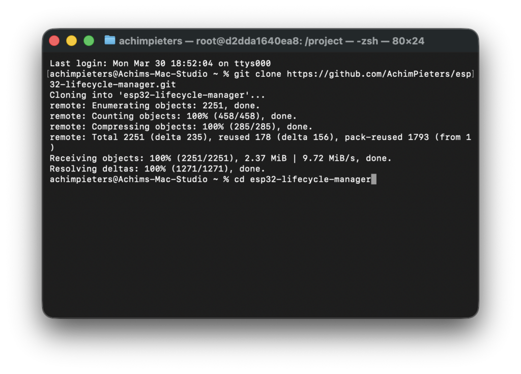
Create your signing keys
We do this now. Not later.
openssl ecparam -name prime256v1 -genkey -noout -out ota_signing_private.pemopenssl ec -in ota_signing_private.pem -pubout -out ota_signing_public.pem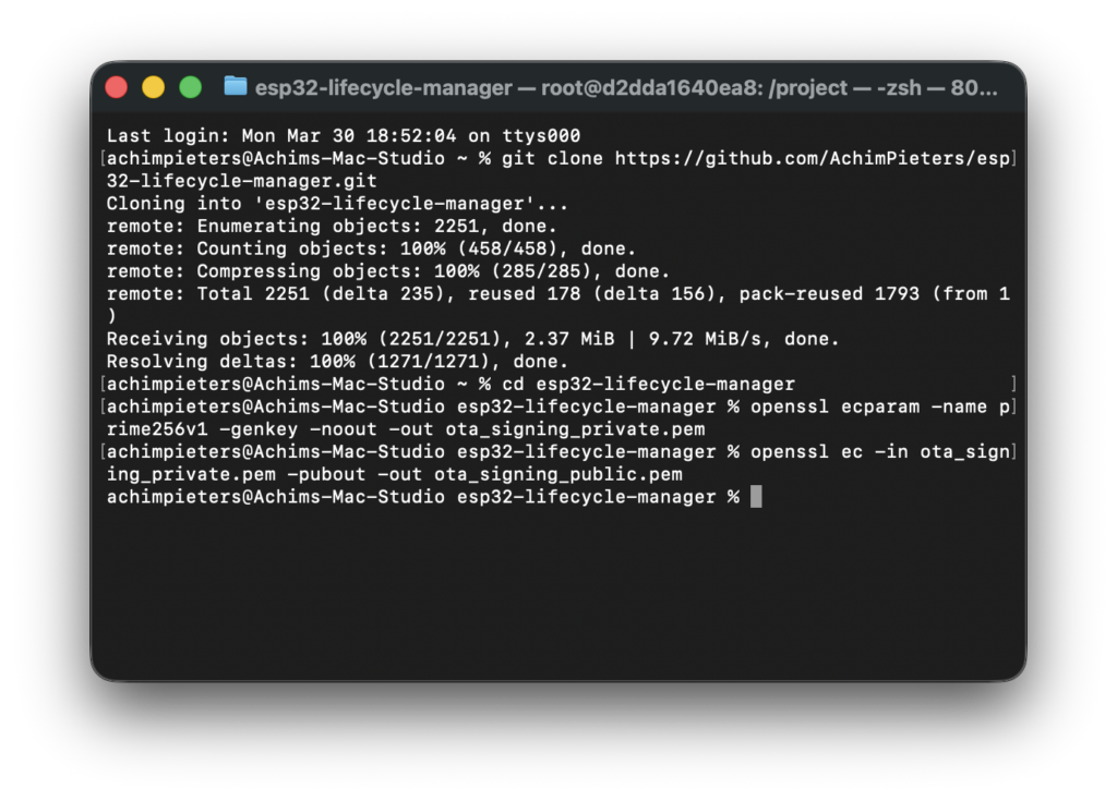
What you now have
- private key → used to sign firmware
- public key → used by LCM
If they don’t match → it will fail.
Now we need a code editor, I what? Don’t worry…
Code editor (explained)
What is a code editor?
A code editor is a program where you:
- open files
- read code
- edit code
- save changes
Think of it as: Word, but for programming.
Which editor do we use?
In this guide we use Pulsar, It is:
- free
- lightweight
- beginner-friendly
- works on Windows, macOS and Linux
Install Pulsar
Download Pulsar, Go to: https://github.com/pulsar-edit/pulsar Click on: Releases and download the version for your OS:
- Windows
- macOS
- Linux
Install it
Run the installer, Accept defaults and finish installation.
Open Pulsar
After installing:
- Start Pulsar
- You will see an empty editor
Open your ESP32 project
In Pulsar:
- Click File → Open Folder
- Select your project folder:
esp32-lifecycle-managerNow you will see:
- folders on the left
- files in the middle
Why we use Pulsar
You don’t need anything complicated. Pulsar lets you:
- edit ESP32 code
- navigate folders easily
- work with multiple files
- stay focused without distractions
Reassurance (important)
You cannot break anything by editing files. Worst case:
- you undo changes
- or re-download the project
So feel free to explore…
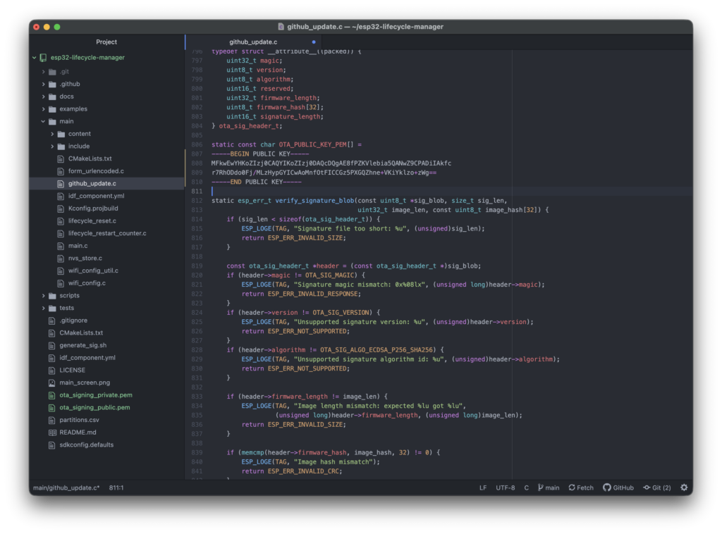
Put the public key into Lifecycle Manager
Open the public key:
ota_signing_public.pem file. Copy the text.
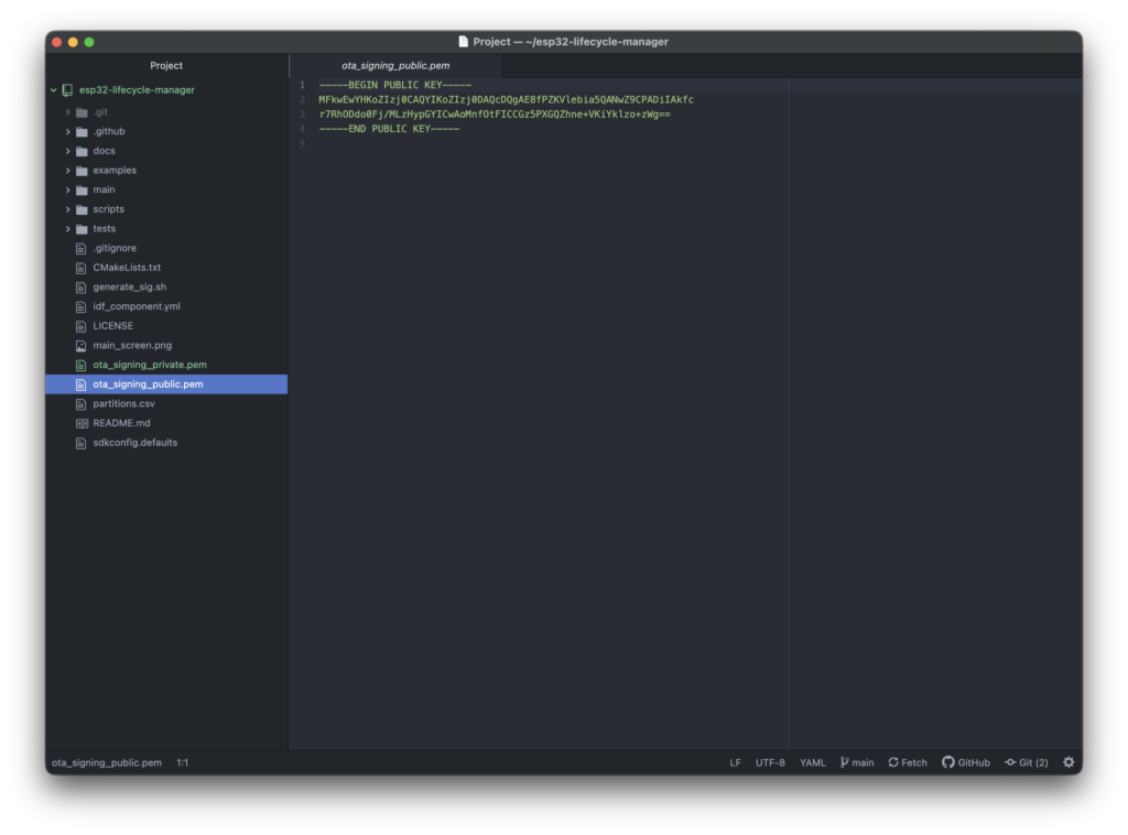
then Open:
main/github_update.cFind:
static const char OTA_PUBLIC_KEY_PEM[] = ...Replace with your key.
Build Lifecycle Manager
docker run -it -v ~/esp32-lifecycle-manager:/project -w /project espressif/idf:v5.4.2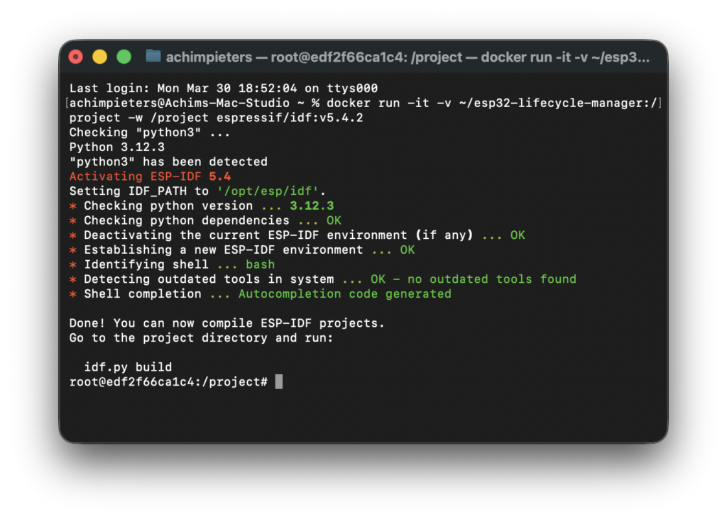
Inside Docker:
idf.py set-target esp32idf.py build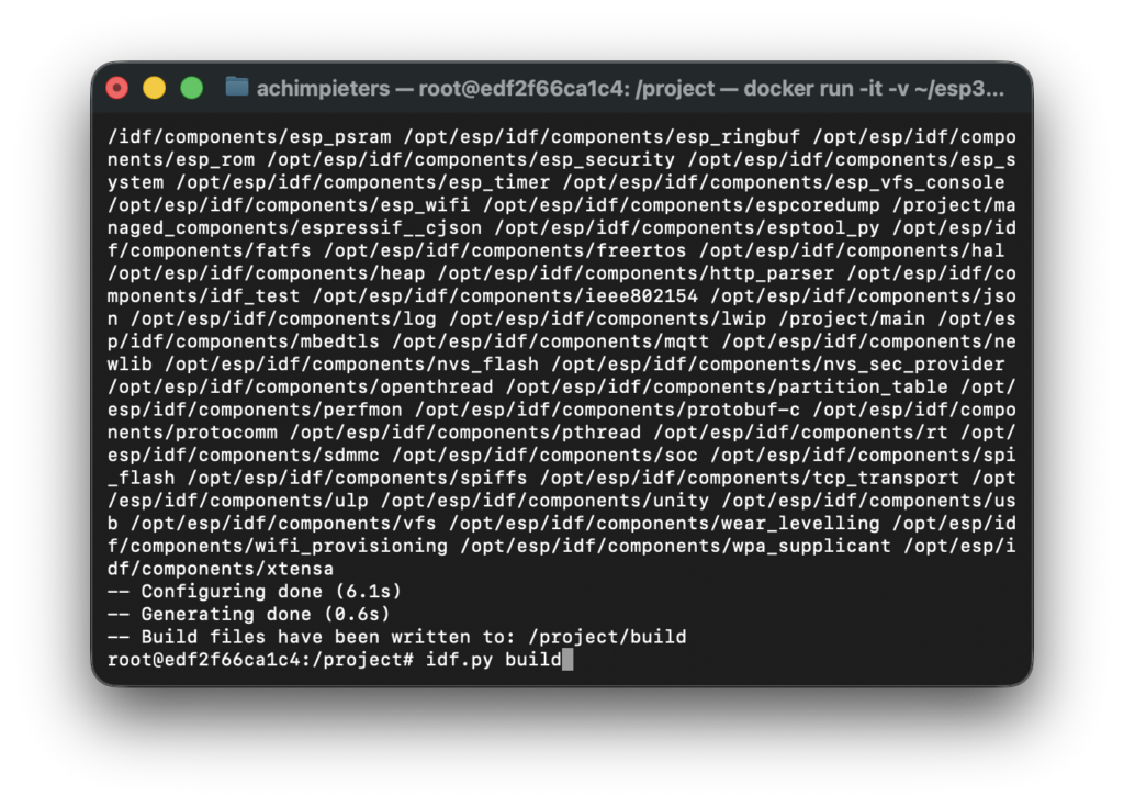
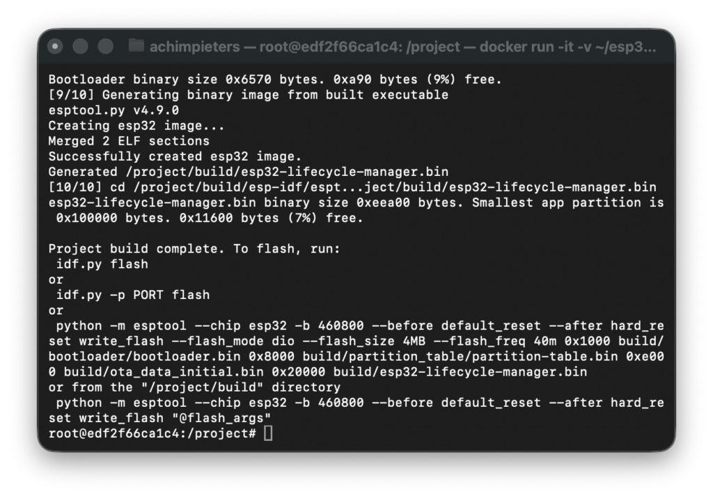
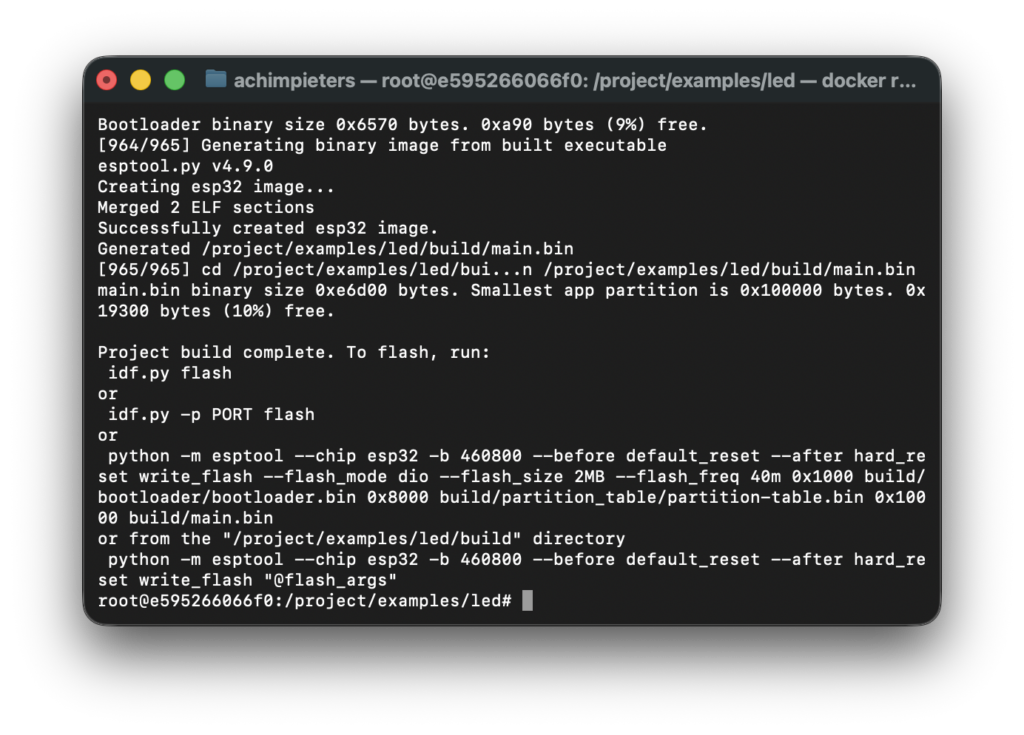
When it is done you see this, keep this window open!
Erase flash (start with a clean ESP32)
Before we upload new firmware, we first erase the ESP32 flash memory. This step is important because:
- the ESP32 may contain old firmware
- leftover data can cause strange or confusing behavior
- starting clean avoids “ghost problems” later
Think of this like: resetting a computer before installing a new operating system. Nothing bad can happen here — erasing flash is safe and reversible.
What does “flash” mean?
The flash is the ESP32’s internal storage. It contains:
- the program (firmware)
- Wi-Fi settings
- configuration data
When we erase it:
- everything is wiped
- the ESP32 becomes “empty”
- ready for fresh firmware
Build your own firmware (LED example)
Now we create your firmware. But instead of creating a new project…
We use something that is already included. Inside the Lifecycle Manager repository: examples/led (This is a HomeKit LED project).
Go to the example
Start the ESP-IDF container
Important: Open a new terminal window!
macOS / Linux
docker run -it -v ~/esp32-lifcycle-manager:/project -w /project espressif/idf:v5.4Windows (example path)
docker run -it -v C:/Users/YOURNAME/esp32-lifcycle-manager:/project -w /project espressif/idf:v5.4What this means (important!):
- Your folder is shared with Docker
- Docker can read & write your files
- ESP32 tools are now available
Your prompt will change. You are now inside the container.
Your first ESP32 Lifcycle manager project
We’ll start with the LED example.
Open the LED example
Inside Docker terminal screen:
cd examples/led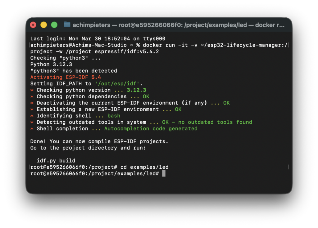
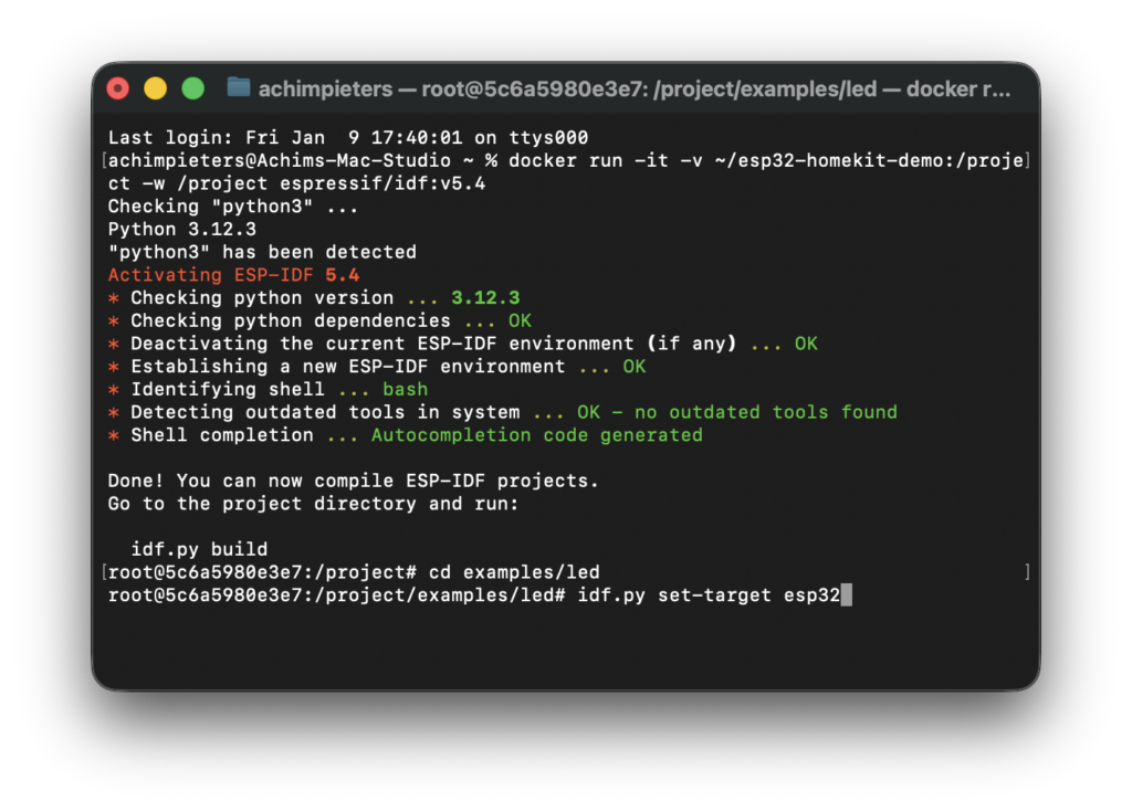
Tell ESP-IDF what chip you use
ESP-IDF needs to know which MCU family you’re compiling for (ESP32, ESP32-C3, ESP32-S3, ESP32-C6, etc.). You set this once per project with idf.py set-target.
idf.py set-target esp32You typically only do this once when starting a project (it configures the build system and creates target-specific settings under build/).
Build the firmware
Compile (turn code into firmware)
idf.py buildThis takes a minute the first time.
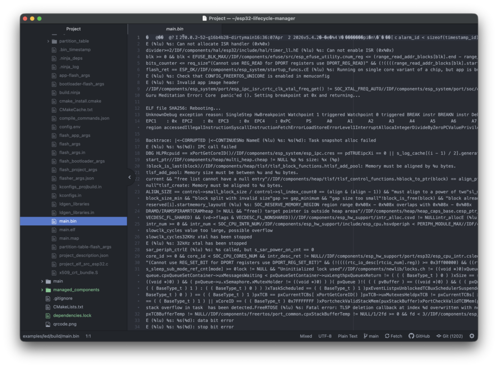
Now the files have been created in the folder main:
main.bin
Sign firmware
Important: Open a new terminal window!
cd ~/esp32-lifecycle-manager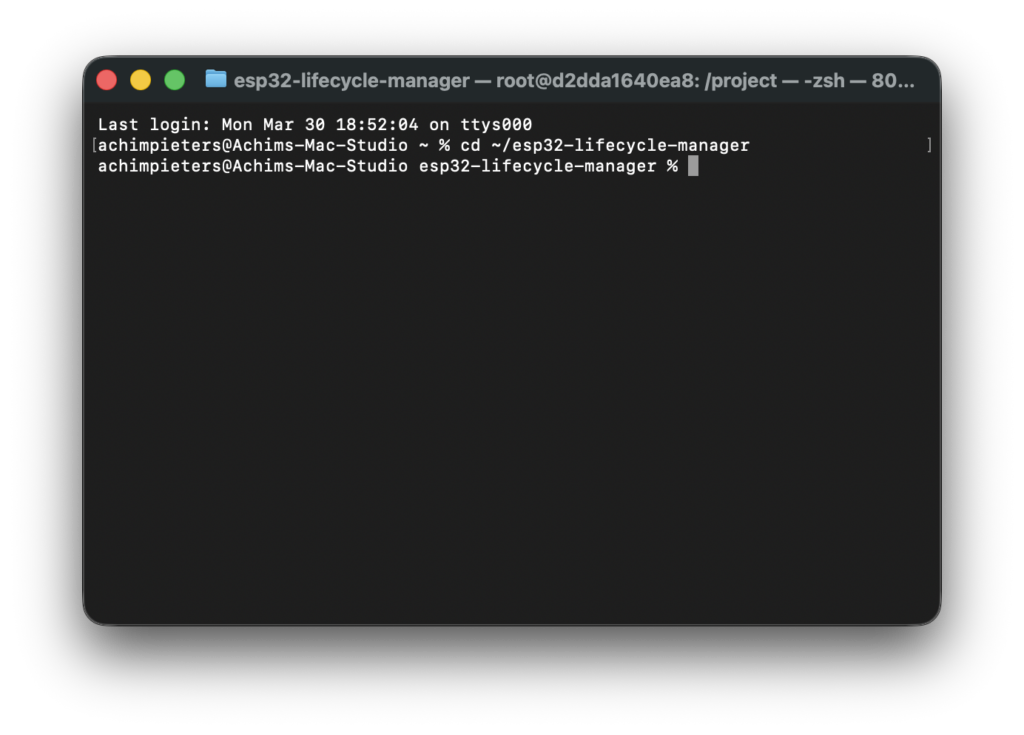
./generate_sig.sh examples/led/build/main.bin ota_signing_private.pem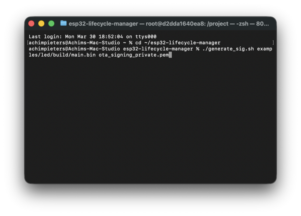
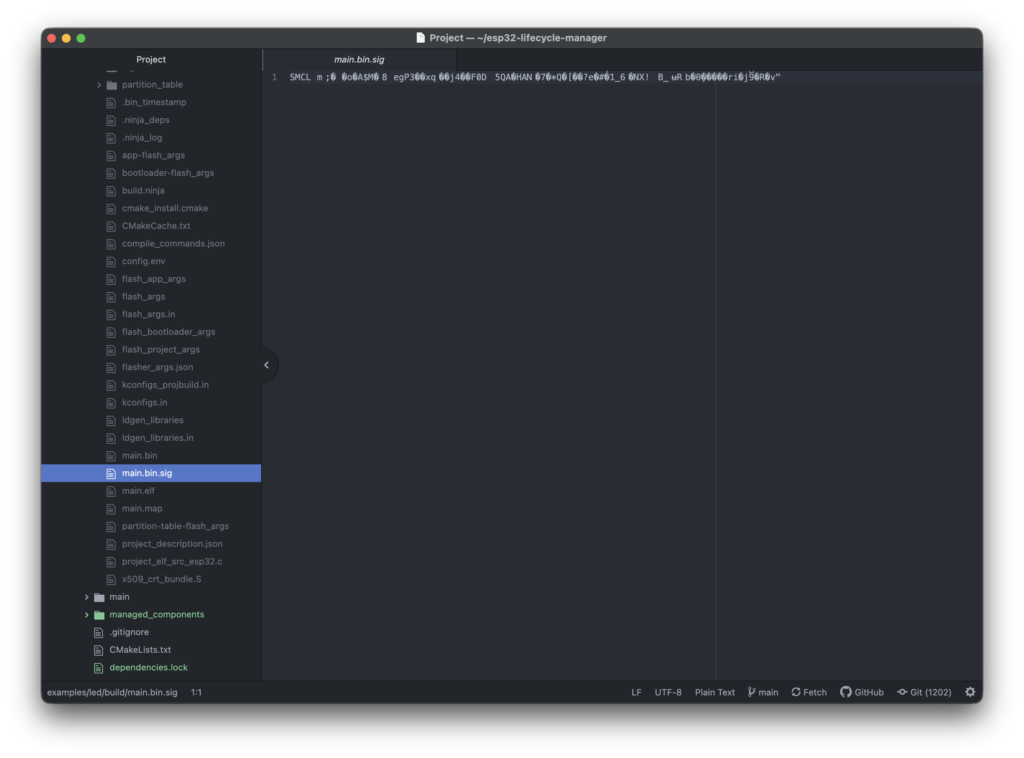
Creates:
- main.bin
- main.bin.sig
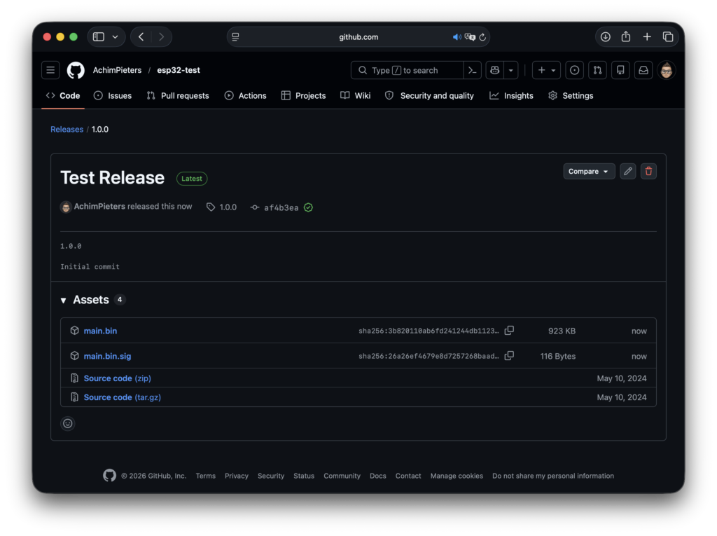
Upload to GitHub
Go to your Github repositories, and create a new one. Once this is done, create a new release, e.g. 1.0.0 Upload both files.
Hardware setup: connecting something you can actually see
Up to now, everything happened on your computer. Now we move to real hardware — but don’t worry, this part is simple and safe. We are going to connect one LED so you can see that your ESP32 and HomeKit accessory are actually doing something.
What hardware do you need for this step?
You need:
- 1 × LED (any color)
- 1 × resistor (220Ω – 1kΩ, anything in that range is fine)
- 2 × jumper wires
- 1 × push button
- A breadboard (recommended, not required)
If your ESP32 dev board already has a built-in LED:
- great — you might not need extra parts
- but external LED is still clearer for beginners
Which pin does the LED example use?
The LED HomeKit example is configured to use: GPIO2
GPIO, what? GPIO, or General-Purpose Input/Output, refers to digital pins on microcontrollers and processors that can be programmed to act as inputs (reading signals from buttons, sensors) or outputs (sending signals to LEDs, motors). So simply said Pin no. 2.
Why GPIO2?
- It is available on most ESP32 boards
- It is safe to use
- Many dev boards already label it clearly
If your board has a built-in LED, it is often connected to GPIO2 — but not always.
This is why we wire our own LED explicitly.
How to connect the LED (slow and clear)
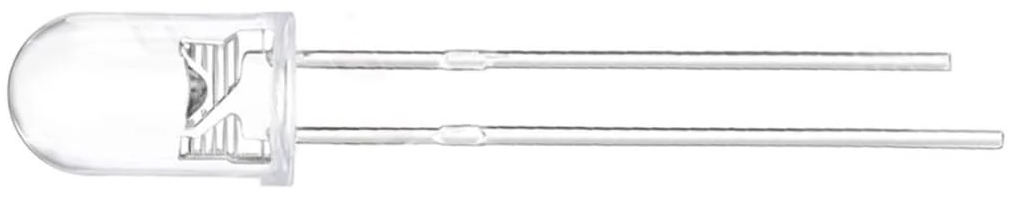
LED basics (important!)
An LED has:
- a long leg → positive (+)
- a short leg → negative (–)
If you connect it backwards, nothing breaks — it just won’t light up.
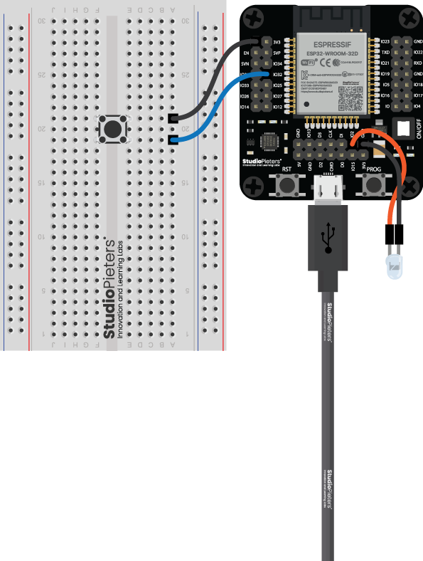
Wiring overview
We are going to connect:
- GPIO2 → resistor → LED → GND
That’s it.
Step-by-step wiring
- Plug the LED into the breadboard
- Connect the long leg of the LED to one end of the resistor
- Connect the other end of the resistor to GPIO2
- Connect the short leg of the LED to GND
That’s the full circuit.
Power the ESP32
Now:
- Plug the ESP32 into USB
- The board powers on immediately
Erase the ESP32 flash
1. Connect the ESP32 to your computer
- Plug the ESP32 into USB
- Use a data cable
- Do not unplug it during this step
If your board has BOOT and RESET buttons:
- keep them in mind (we may need them)
2. Open a terminal
Make sure you are outside Docker for this step (PowerShell, Terminal, etc. on your normal system).
cd ~/esp32-lifecycle-manager
3. Run the erase command
Type the following command and press Enter:
esptool.py erase_flash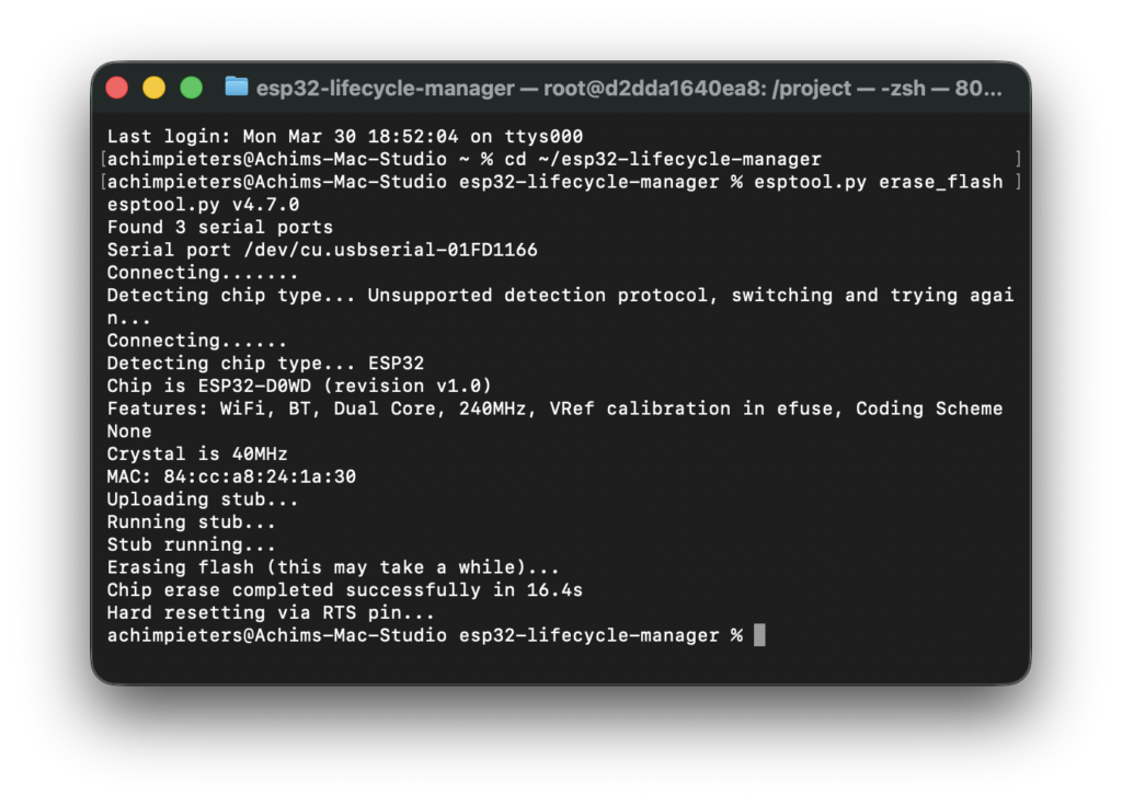
What happens now?
When you run this command, two things happen at once:
1. The ESP32 flash is erased
You’ll see messages like:
- “Connecting…”
- “Chip is ESP32”
- “Erasing flash…”
When it finishes, the ESP32 is completely clean.
2. The serial port name is detected
While erasing, esptool.py automatically shows the port name your ESP32 is using. in this case: Serial port /dev/cu.usbserial-01FD1166
Examples you might see:
- macOS
/dev/cu.usbserial-XXXX/dev/cu.SLAB_USBtoUART - Linux
/dev/ttyUSB0/dev/ttyACM0 - Windows
COM3COM4
Important: Write this port name down — you will need it in the next step when screening the module.
If it does NOT connect (very common for beginners)
Don’t panic — this is normal. Try this:
- Hold the BOOT button
- Press and release RESET
- Release BOOT
- Run the command again:
esptool.py erase_flash
Many ESP32 boards need this once to enter programming mode.
What success looks like
You are successful when:
- The erase command finishes without errors
- You see a port name
- No scary red error messages remain
At this point:
- ESP32 is clean
- Communication works
- You know the correct serial port
Important reassurance
After erasing:
- the ESP32 will not run anything
- LED’s may stay off
- that is expected
You have not broken anything. You have prepared the ESP32 properly.
Flash firmware
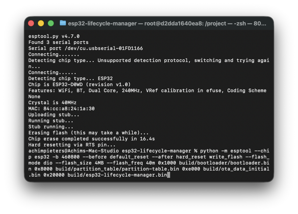
Remember the terminal screen that you had to have open under the part “Build Lifecycle Manager” above, this is why. Copy the lines: python -m esptool –chip esp32 -b 460800 –before ………
python -m esptool --chip esp32 -b 460800 --before default_reset --after hard_reset write_flash --flash_mode dio --flash_size 4MB --flash_freq 40m 0x1000 build/bootloader/bootloader.bin 0x8000 build/partition_table/partition-table.bin 0xe000 build/ota_data_initial.bin 0x20000 build/esp32-lifecycle-manager.bin
And paste it in your new window and press enter.
Watch it boot (seeing life signs from your ESP32)
At this point:
- Lifecycle Manager is flashed
- the ESP32 has power
- but you can’t see what it’s doing yet
To understand what’s happening inside the ESP32, we use a serial monitor. Think of this as: a text window where the ESP32 tells you what it’s doing while it boots
hat is a serial monitor?
A serial monitor:
- shows messages sent from the ESP32 over USB
- lets you see:
- boot messages
- Wi-Fi connection status
- Startup information
- error messages (if something goes wrong)
If something doesn’t work, this is where you look first.
Open the serial monitor
Make sure the ESP32 is connected
- ESP32 plugged into USB
- Same USB port as when flashing
- No other program using the port
Close:
- Other terminal sessions using the same port
Only one program can use the serial port at a time.
2. Open a terminal (outside Docker)
OPen a new terminal window:
- Windows → PowerShell
Press the “Windows” key + “R” on your keyboard to open the Run dialog. Type “powershell” into the Run dialog. Press “Ctrl” + “Shift” + “Enter” on your keyboard or press “OK” to open PowerShell with elevated privileges. - macOS → Terminal
You can open Terminal on macOS quickly using Spotlight Search (Command + Spacebar, then type “Terminal”) or by navigating through Finder to the/Applications/Utilities/folder and double-clicking the Terminal app, both methods providing the command-line interface for your Mac. - Linux → Terminal
To open the Linux Terminal, the fastest way is the shortcutCtrl + Alt + T, but you can also find it in the applications menu by searching for “Terminal,” right-click the desktop for an “Open Terminal” option, or use theAlt + F2run dialog and typegnome-terminal(orkonsole/xfce4-terminal).
3. Start the serial monitor
Use the same port name you saw during flashing. Example (macOS):
screen /dev/cu.usbserial-XXXX 115200What this means:
screen→ simple serial monitor tool/dev/cu.usbserial-XXXX→ your ESP32 USB port115200→ communication speed (baud rate)
After pressing Enter:
- the terminal may go blank
- that is normal
Reset the ESP32 (if needed)
If you see nothing immediately:
- press the RESET button on the ESP32
Text should start scrolling.
What you should see (this is the important part)
During a normal boot, you will see messages like:
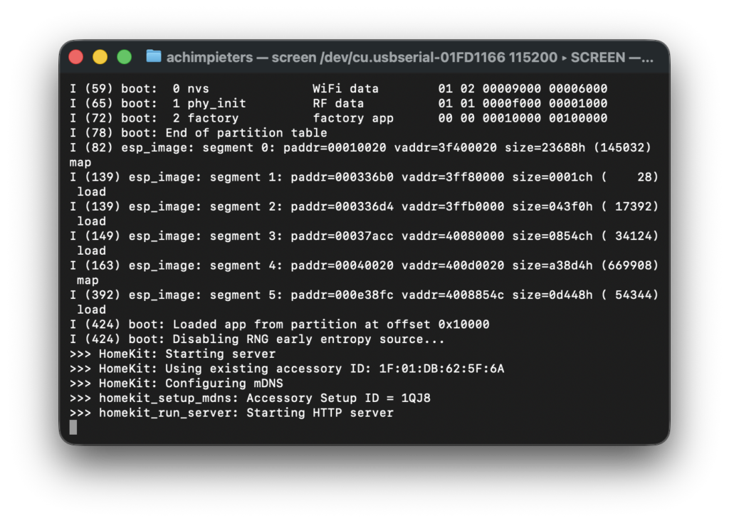
1. ESP32 boot information
- chip information
- memory setup
- system startup
This proves: That the firmware is running and the ESP32 is alive
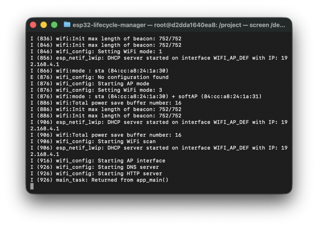
2. LCM messages
You should see lines indicating:
- Starting AP interface
- Starting DNS server
- Starting HTTP server
This proves: That the LCM is running and the network is reachable
How to exit the serial monitor
screen doesn’t exit like normal programs. To exit safely:
- Press CTRL + A
- Then press K
- Press Y to confirm
This:
- closes the serial session
- releases the USB port
- allows flashing or reconnecting later
Important beginner reassurance
If you:
- see text scrolling
- even if you don’t understand it all
That is success.
You are not expected to understand every line yet. Right now, you are only checking:
“Is my ESP32 alive and doing something reasonable?”
And if it is — you’re on the right track.
What comes next
You can move on to: Installing your firmware trough LCM. This is the moment where everything comes together — and yes, it’s normal to feel a little excited here!
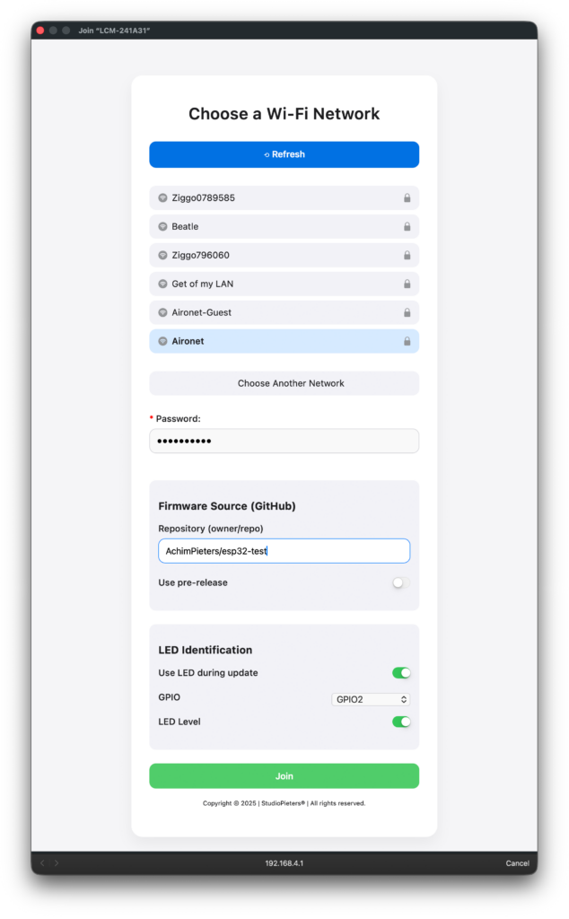
Open the captive portal
Once you installed the Lifecycle Manger on the ESP32 it will automatically startup an Access Point (AP) and Captive Portal. you can find it trough searching the Wi-Fi connections it wil look like:
LCM-XXXXXX
On a MacOs, it can take sometimes a few minutes.
Select your Wif-Fi Network and enter the password. Then tell Lcm where he can find your main.bin and main.bin.sig e.g. AchimPieters/esp32-test. Then you have the ability to use the LED during update. Enabling this option will make the LED blink during the installation and update of the firmware. Ofcourse LCM needs to know on which GPIO you connected the LED and if it is enabled by pulling it low or putting it high. Default it is high by enabling it is it put to low.
OTA happens
LCM will:
- download
- verify
- install
- reboot
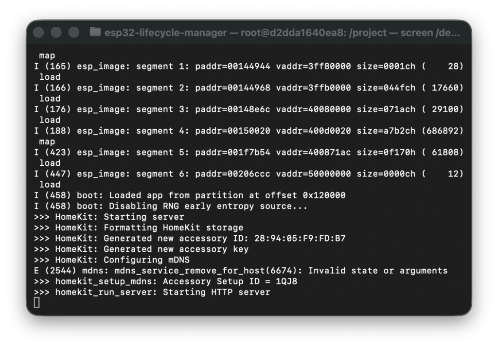
What comes next
Once you’ve seen:
- Wi-Fi connected
- HomeKit started
You can move on to: Adding the accessory to Apple Home. This is the moment where everything comes together — and yes, it’s normal to feel a little excited here!
Add the ESP32 accessory to Apple Home
This step is where many beginners get confused — and that’s normal.
Your ESP32 is running a DIY HomeKit accessory, which means:
- it is not Apple-certified
- the Home app will show extra warning screens
- this is expected and safe
Nothing is wrong with your setup.
Before you start
Make sure:
- Your ESP32 is powered on
- It has successfully connected to Wi-Fi (check serial logs)
- You have your iPhone or iPad connected to the same Wi-Fi network
If HomeKit pairing fails, it’s almost always a Wi-Fi issue.
Step-by-step: adding accessory
1. Open the Home app
On your iPhone or iPad:
- Open the Home app
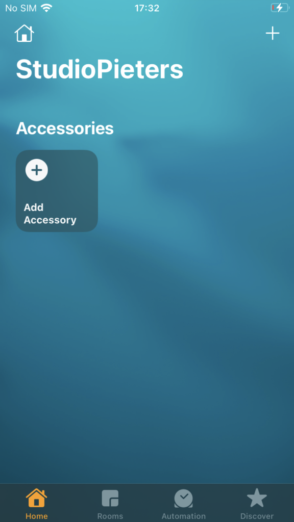
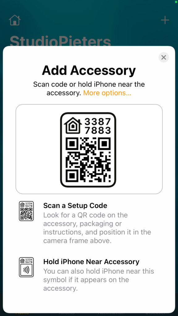
2. Start adding a new accessory
- Tap the + button (top right)
- Choose Add Accessory
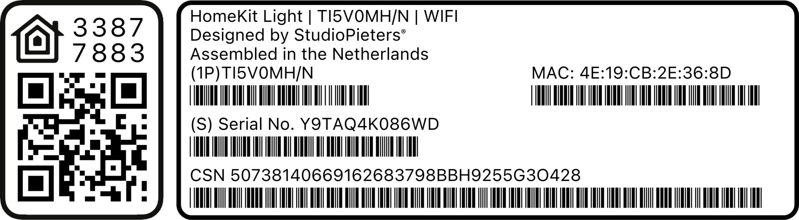
3. Scan the QR-Code
When asked to scan a code
4. Select your ESP32 accessory
After a moment, you should see:
- a new accessory appear in the list
- often with a generic name like “Accessory” or “HomeKit LED”
Tap it.
5. Accept the uncertified accessory warning
This is the important part. Apple will show a warning like:
“This accessory is not certified and may not work reliably.”
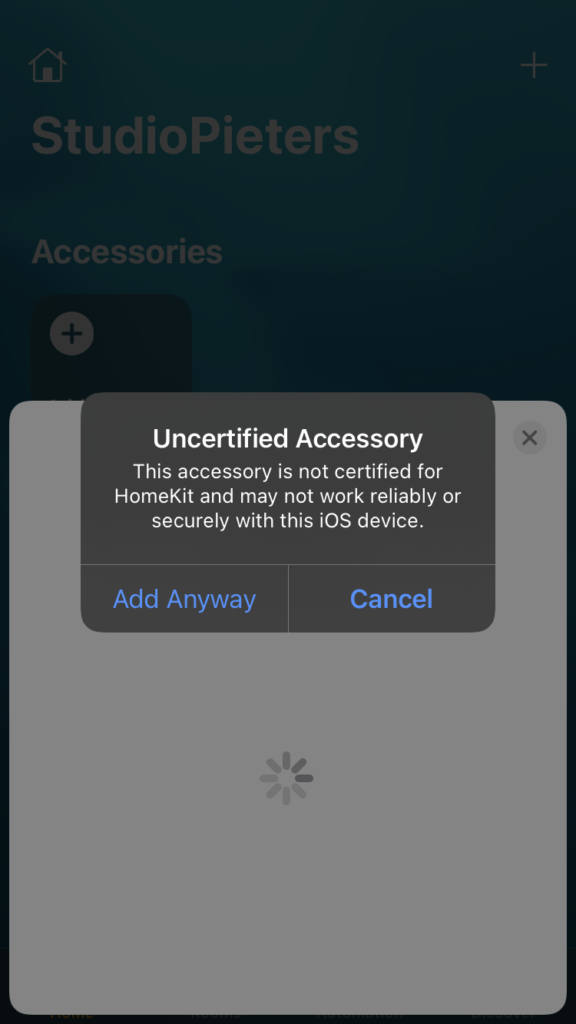
This is normal for DIY HomeKit devices. To continue:
- Tap Add Anyway
- You may have to tap Add Anyway again
You are not doing anything unsafe. Apple just wants to protect beginners from unknown devices.
6. Assign room and name (optional but recommended)
Apple will ask:
- Which room is this accessory in?
- What should it be called?
These steps are optional, but helpful.
Example names:
- “ESP32 LED”
- “Test Light”
- “HomeKit Demo”
Test it
Once added:
- The accessory appears in the Home app
- Tap it ON → LED turns on
- Tap it OFF → LED turns off
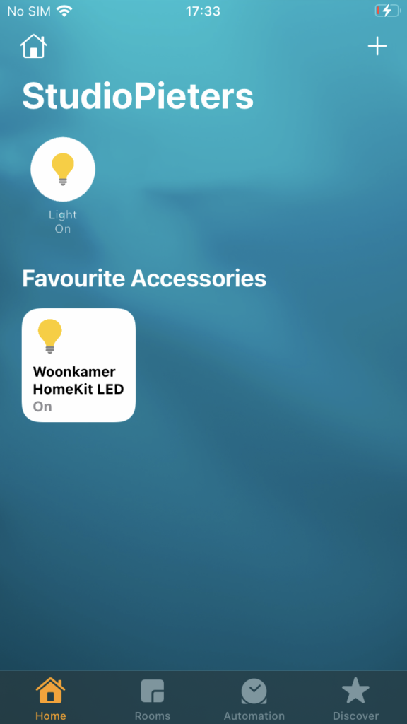
If that works:
If you reached this point:
- ESP32 boots
- Wi-Fi connects
- HomeKit pairs
- LED responds
You’ve crossed the hardest mental barrier.
From here on:
- improving behavior
- adding features
- building your own accessory
…is learning, not fear.
Update, Reset and Recovery Options
LCM supports multiple reset mechanisms and an update mechanism:
- Firmware update: Trough the Eve app.
- Software factory reset: via the LCM API, clear all configuration and restart by using the button.
- Hardware factory reset: if you power-cycle or restart the ESP32 ten times in a row, LCM detects this pattern, waits ~11 seconds, then wipes config and restores defaults.