We have used a legacy GNU Makefile build in the previous HomeKit LED Example. Now need to migrate to CMake. A lot of people first getting into this wonderful space of embedded system design do so through Arduino, which uses C++ with many built-in functions. The new ESP-IDF uses CMake to configure the build system. For more information on CMake, you can visit their website at cmake.org.

HomeKit led
A Hello world program is a simple computer program that does nothing but display the text “Hello world” on the screen. Such a program is usually used as the first example in a programming course in a particular programming language or environment. It is also used to verify that the necessary basic programming environment is in place and functioning. This basic example is then used in the course as a stepping stone to writing more advanced programs. In line with this, various computer language courses and books also use a Hello world variant as a first introduction and starting example.
As far as we know, the first version of Hello world was used by the makers of the C programming language to showcase their programming language. It demonstrates the basic aptitude of a programming language to communicate with a user through an output device.
We use an LED that we can turn on and off as a hello world example for HomeKit.

Prerequisites
Before we can start with the ESP32 – HomeKit LED example, you need to install the compiler for all ESP32 XX chips. Okay, things have got a bit more complicated than we are used to. Since the arrival of the ESP32 module, Espressif the maker of the ESP modules has also worked hard behind the scenes. They have developed IDF. IDF is the compiler for all ESP32 XX chips. So, for HomeKit Development. Let’s start with setting up the development environment first.
So read this blog first: ESP32 – Developing With ESP-IDF before proceeding.

ESP32 – HomeKit Repository
For those who have been following my blogs for some time, you know that I started with ESP8266 HomeKit. Meanwhile, the ESP has been further developed and the ESP32 is the “replacement” of the ESP8266. The development environment has also changed and has now become ESP-IDF. So it’s time for a new HomeKit Repository.
So read this blog first: ESP32 – HomeKit Repository before proceeding.
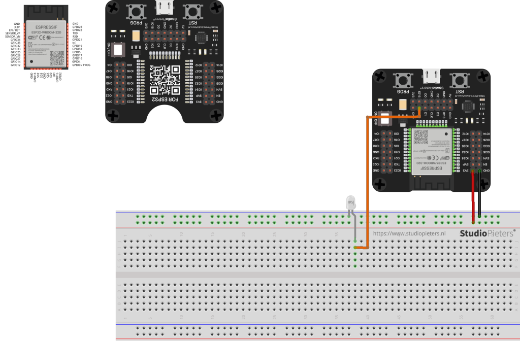
HomeKit LED Hardware
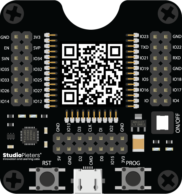
For my test setup, I will use a ESP32 programmer. This is a programmer for the ESP32 WROOM format IC’s from Espressif (does not include the ESP32 Module). The programmer allows the ESP32-WROVER to easily mount or dismount to the programmer. This test board allows you to program the ESP32 without having to soldering the ESP32 Module. It is more innovative than other ESP32 board. The module uses the CP2104 USB to Bridge Chip onboard, two LED indicate the UART TX/RX, and It also supports auto-download circuit. The input is +5V Power from Micro USB connector, the output is 3.3V 800mA LDO with a Switch. All ESP32 pin are available with male headers. So ideal to make a test setup.
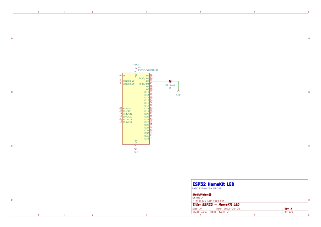
HomeKit LED Scheme
A schematic, or schematic diagram, represents the elements of a system with abstract and graphic symbols instead of realistic pictures. A schematic diagram focuses more on comprehending and spreading information rather than doing physical operations. For this reason, a schematic usually omits details that are not relevant to the information that it intends to convey and may add simplified elements to help readers understand the features and relationships.
Software Preparation
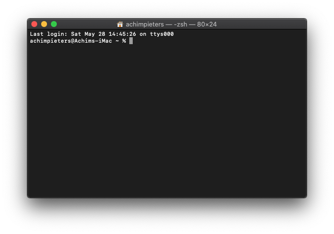
When you followed the instructions in the ESP32 – Developing With ESP-IDF blog, your development environment is set up. Open A terminal window.
Opening Terminal through the Finder
1. On the left toolbar, click “Applications“.
2. Scroll down and open the “Utilities” folder.
3. Double click “Terminal” to launch it.
Now we need to clone the ESP32 – HomeKit Demo repository. The git clone command creates a clone or copy of an existing repository in a Folder. It is the most commonly used command that allows users to obtain a development copy of an existing central repository. The git clone initializes a copy of the repository on the local machine. Then you can start editing files in the project so that they are ready to compile. Type the line below and press Enter.
git clone --recursive https://github.com/AchimPieters/esp32-homekit-demo.git
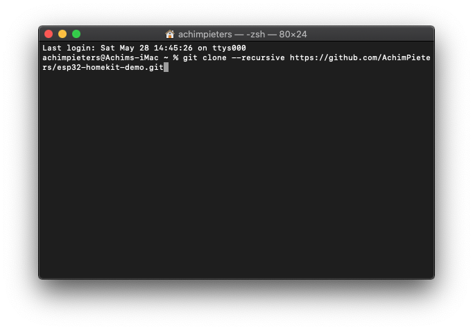
All files will be copied into the esp32-homekit-demo folder.
Configure
The configuration of your code has also changed with the arrival of ESP-IDF. We will do this through a terminal window. Open a new terminal window.
Note: for this part to work, you must have read this blog first: ESP32 – Developing With ESP-IDF before proceeding.
Opening Terminal through the Finder
1. On the left toolbar, click “Applications“.
2. Scroll down and open the “Utilities” folder.
3. Double click “Terminal” to launch it.
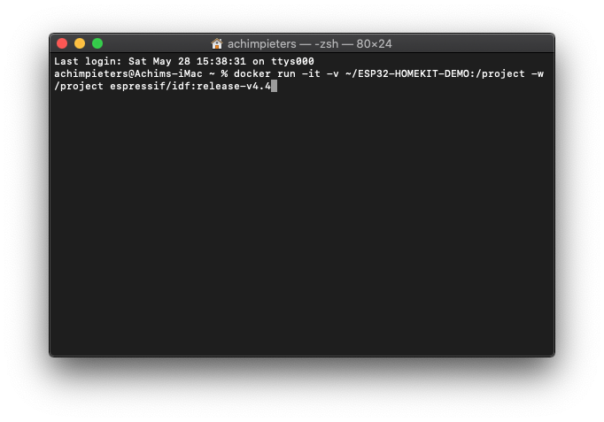
Next you execute the following command, where the path is the place, where on macOS, we stored our GitHub repo. Type the following line in your terminal window en press enter.
Docker run -it -v ~/ESP32-HOMEKIT-DEMO:/project -w /project espressif/idf:release-v4.4
Note: the idf:release-v4.4 version has to be the same you installed. At this time of writing, it is release-v4.4.
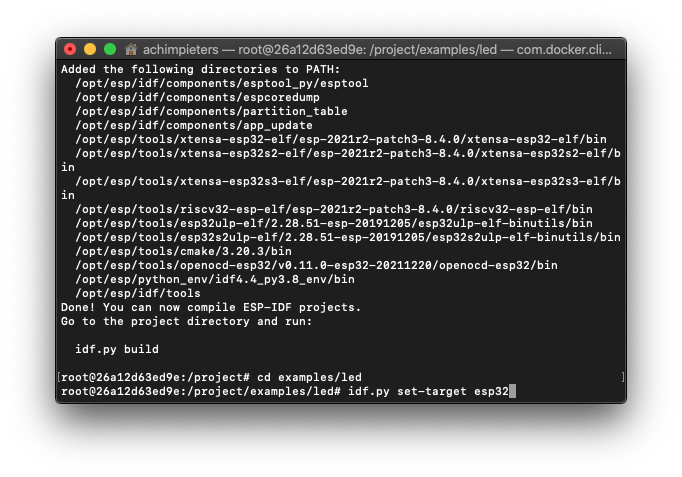
Now we have connected to the Docker container and set the work directory to our esp-homekit-demo folder. Now let change in to our example’s directory, followed by the accessory we want to make by typing the following line:
cd examples/led
ESP-IDF supports multiple targets (chips). A full list of supported targets in your version of ESP-IDF can be seen by running idf.py –list-targets. To select the target before building the project, we need to set the chip. In this case, the “standard” ESP32. We do so by typing:
idf.py set-target esp32
Now we get to the good part, the configuration of our setup. We open the menu for configuration by typing the following line:
idf.py menuconfig
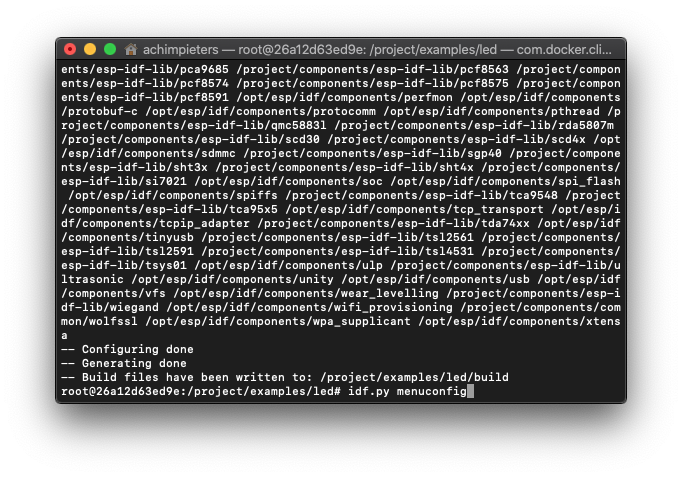
When the configuration menu is loaded, you will see this screen. Now we select StudioPieters from the menu.
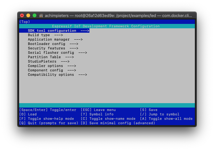
Here we have all the option combined to get our ESP32 HomeKit accessory up and running! Nice Huh! This menu configuration makes it possible for people with less programming skills to configure and make their own ESP32 HomeKit accessories!
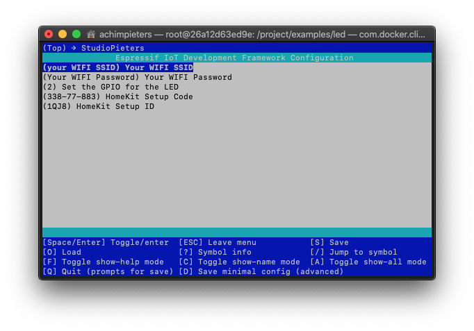
In this menu, we see the following options:
– (Your Wi-Fi SSID) Your Wi-Fi SSID. → Fill in your Wi-Fi SSID (Required)
– (Your Wi-Fi Password) Your Wi-Fi Password → Fill in your Wi-Fi Password (Required)
– (2) Set the GPIO for the LED → If you want to change the GPIO for the LED, you can do that here
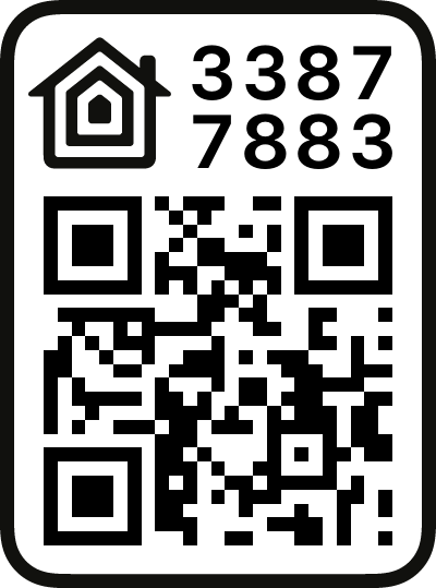
– (338-77-883) HomeKit Setup Code → If you want to change the HomeKit Setup Code, you can do that here (Note: you need to make a new QR-CODE To make it work)
– (1QJ8) HomeKit Setup ID → If you want to change the HomeKit Setup ID, you can do that here (Note: you need to make a new QR-CODE To make it work)
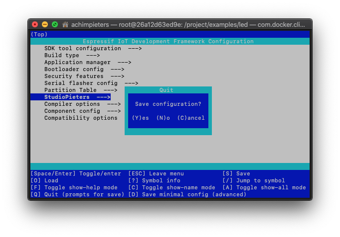
Once you have made your changes, exit the menu and save the configuration.
Build the Project
Now we start with the fun part! We are going to build the project. We will do this through a terminal window. Open a new terminal window.

idf.py build
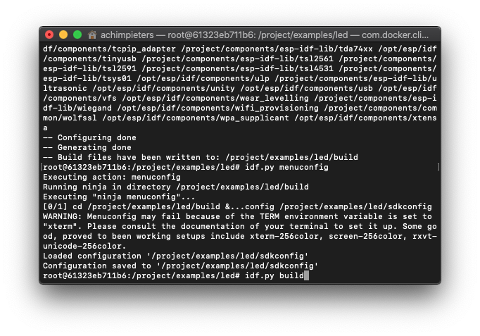
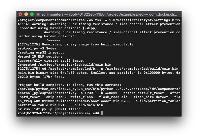
When the compiling is done, you will see some instructions in the screen. It will say something like
esptool.py -p (PORT) -b 921600 write_flash --flash_mode dio --flash_size detect --flash_freq 40m 0x10000 build/main.bin build 0x1000 build/bootloader/bootloader.bin 0x8000 build/partition_table/partition-table.bin
You can close this terminal window.
Flash the ESP32
The files are ready for being flashed to the ESP32 module. We will do this through a terminal window. Open a new terminal window.
Opening Terminal through the Finder
1. On the left toolbar, click “Applications“.
2. Scroll down and open the “Utilities” folder.
3. Double click “Terminal” to launch it.
Before you can flash your chip, you need to connect it to your Mac, and run the following command to find the port it’s connected to.
ls /dev/tty.*
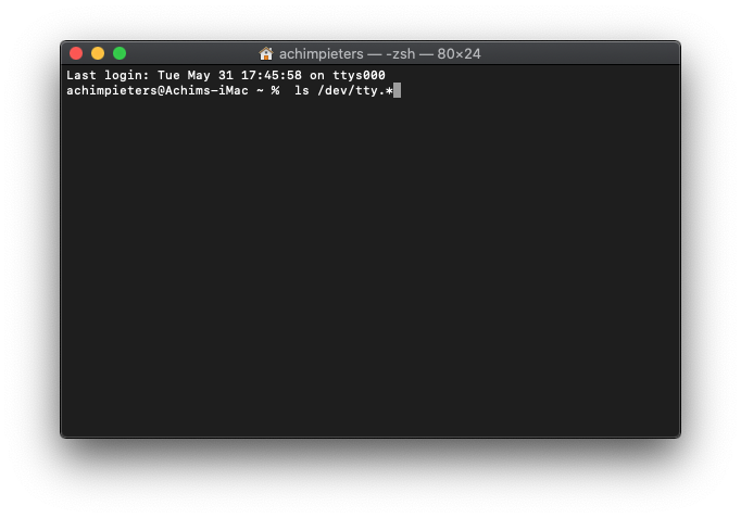
This will show you the (PORT) that your device is connected to. In this case, /dev/tty.usbserial-01FD1166.
Now you can do the following command where you replace the (PORT) with the revealed port /dev/tty.usbserial-01FD1166.
esptool.py -p (PORT) -b 921600 write_flash --flash_mode dio --flash_size detect --flash_freq 40m 0x10000 build/main.bin build 0x1000 build/bootloader/bootloader.bin 0x8000 build/partition_table/partition-table.bin
Change into the esp32-homekit-demo directory, followed up by the examples directory and then the LED directory. In this case, it is:
cd /users/achimpieters/esp32-homekit-demo/examples/led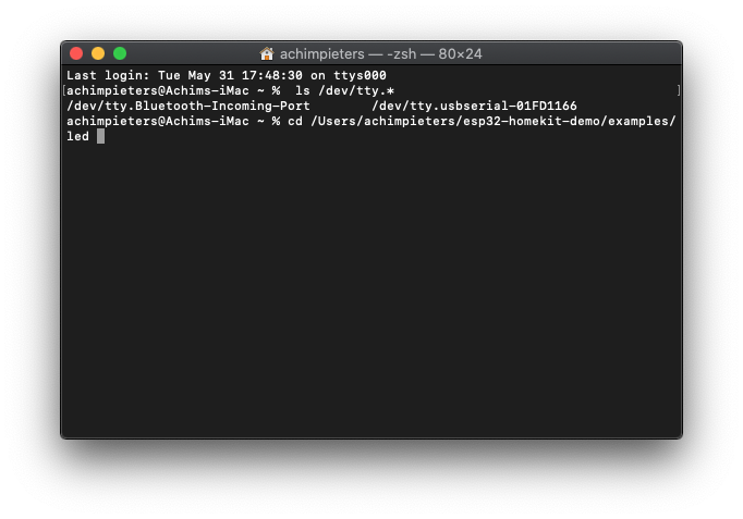
Once we changed into the directory, we can give our flash command.
esptool.py -p /dev/tty.usbserial-01FD1166 -b 460800 --before default_reset --after hard_reset --chip esp32 write_flash --flash_mode dio --flash_size detect --flash_freq 40m 0x1000 build/bootloader/bootloader.bin 0x8000 build/partition_table/partition-table.bin 0x10000 build/main.bin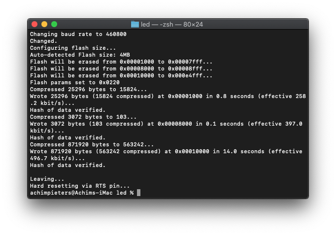
When your ESP32 module is flashed, you can close the Terminal window.
Note: If you want to see what’s happening on your ESP module, you can open a new terminal window.
Opening Terminal through the Finder
1. On the left toolbar, click “Applications“.
2. Scroll down and open the “Utilities” folder.
3. Double click “Terminal” to launch it.
And run the following command:
screen /dev/tty.usbserial-01FD1166 115200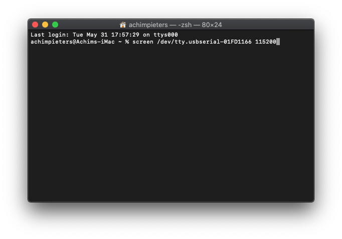
Connection with HomeKit
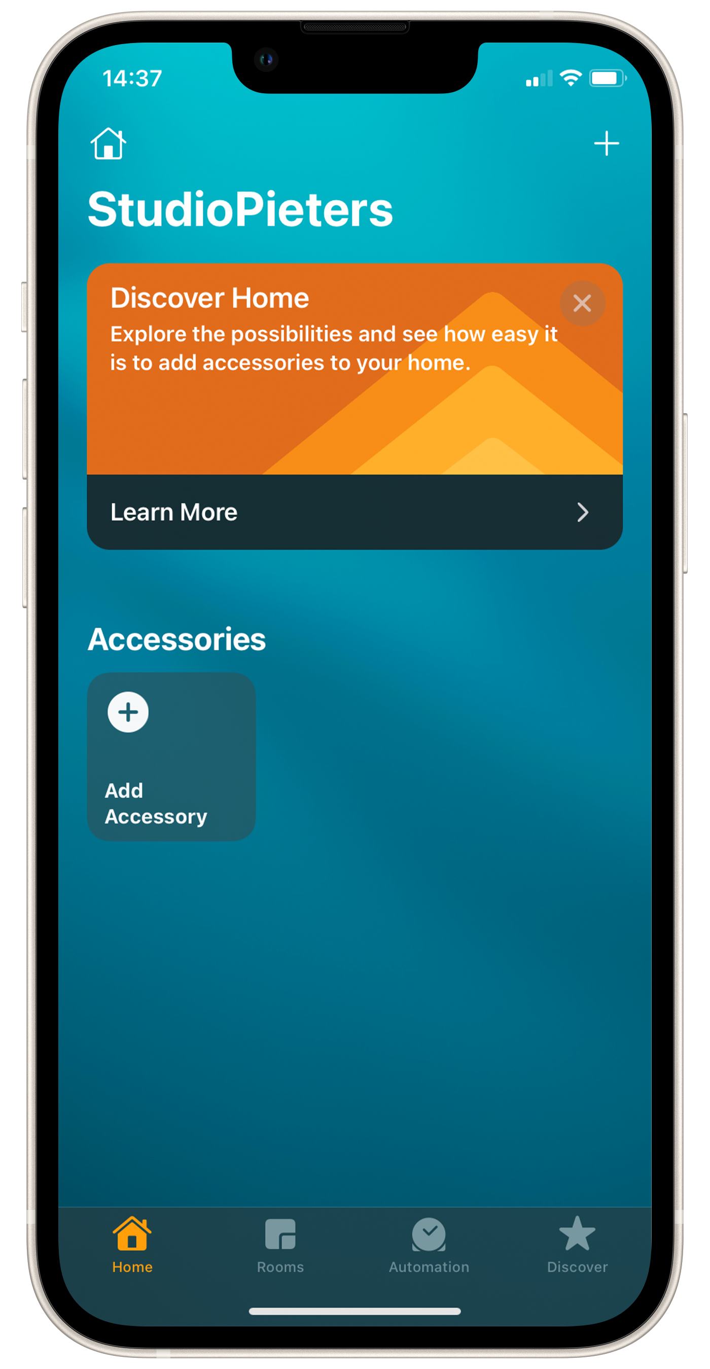
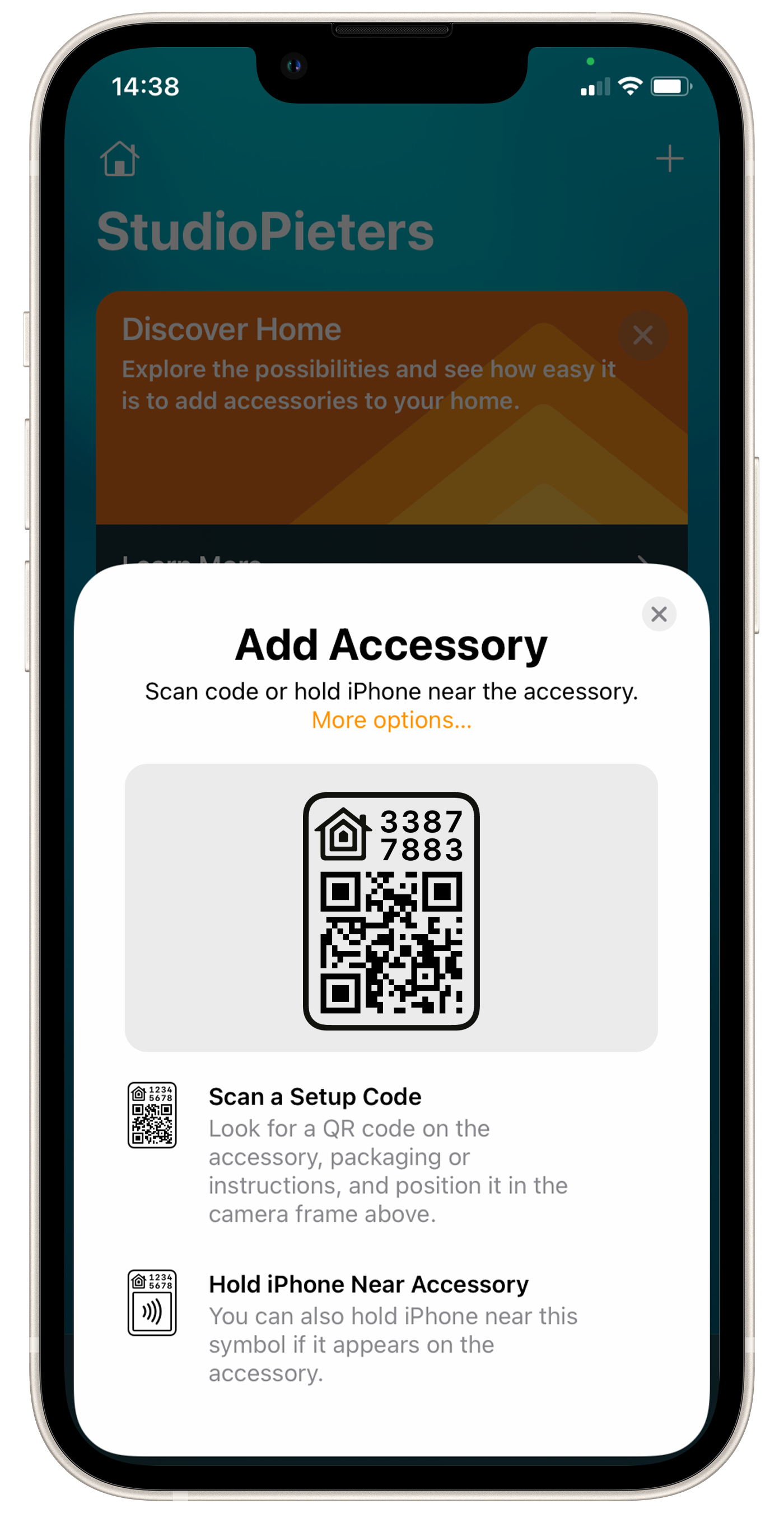
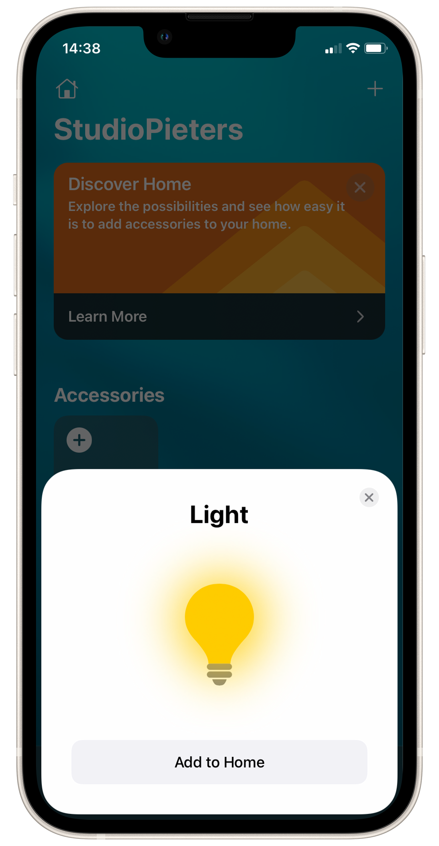
The moment of truth, now we will see if it works. Open your HomeKit App. And scan the QR Code here below.
 |  |  |
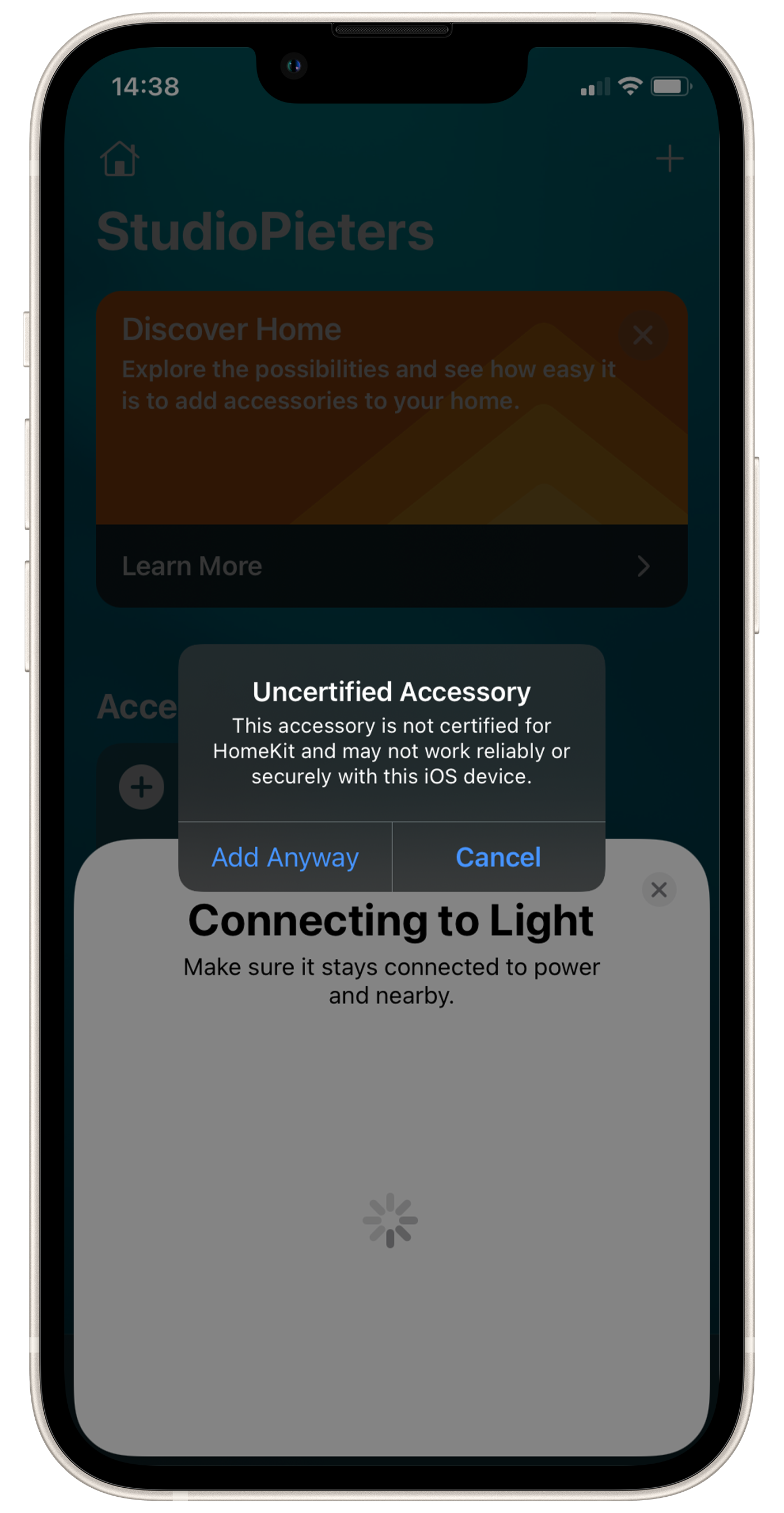
After scanning HomeKit will find your device as A Light, press Add to home. The HomeKit will prompt you that it is an Uncertified Accessory, click Add Anyway.
 |  |
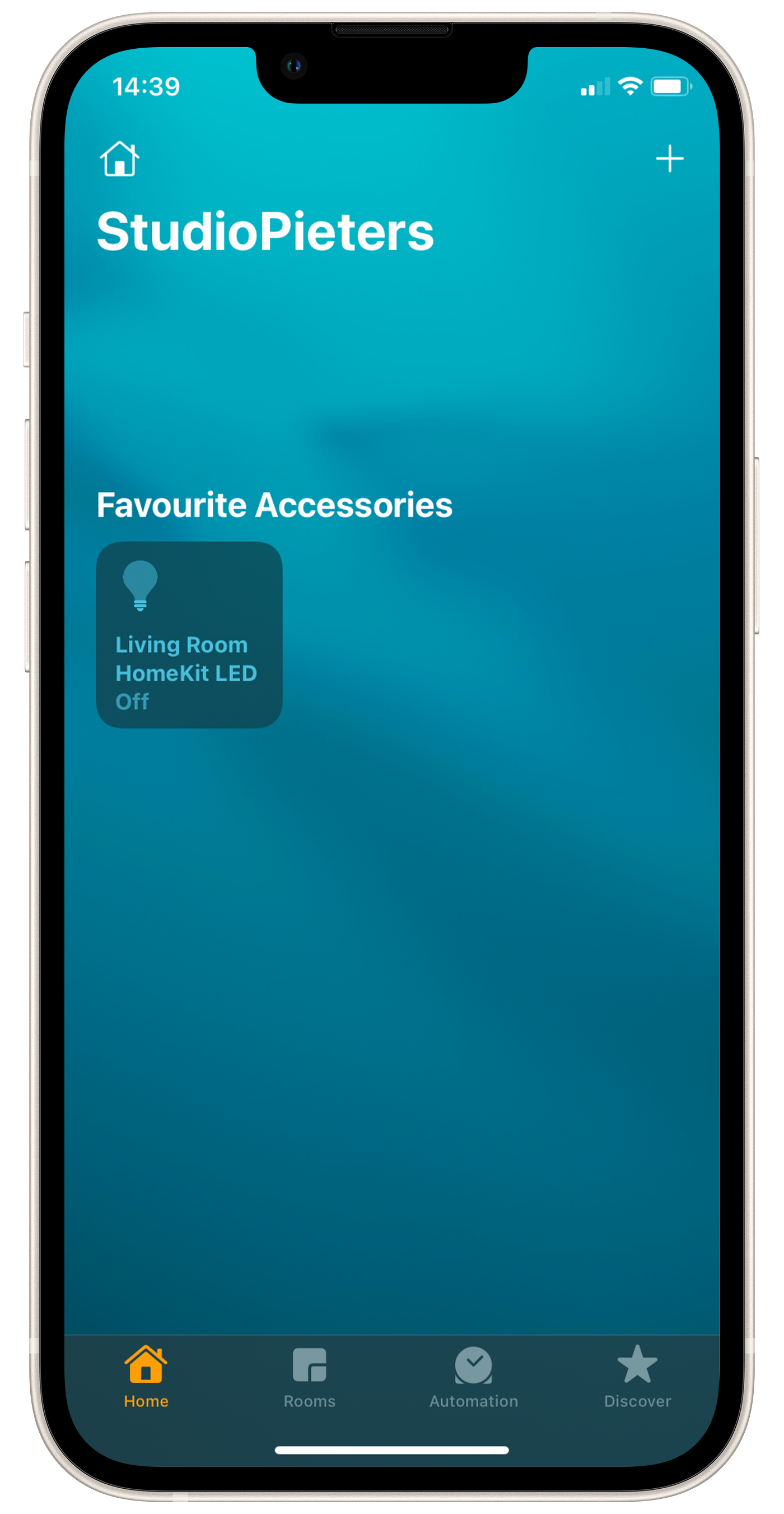
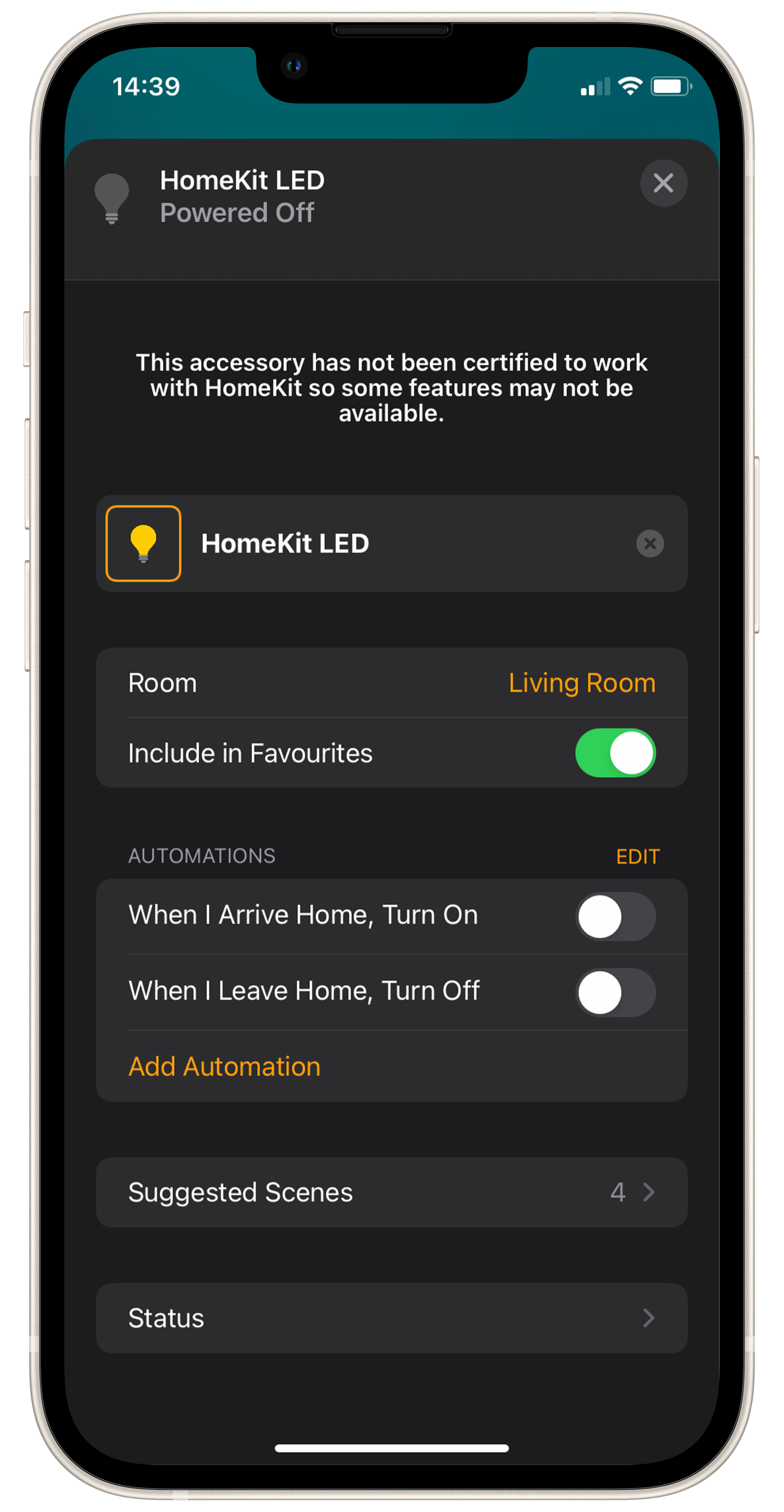
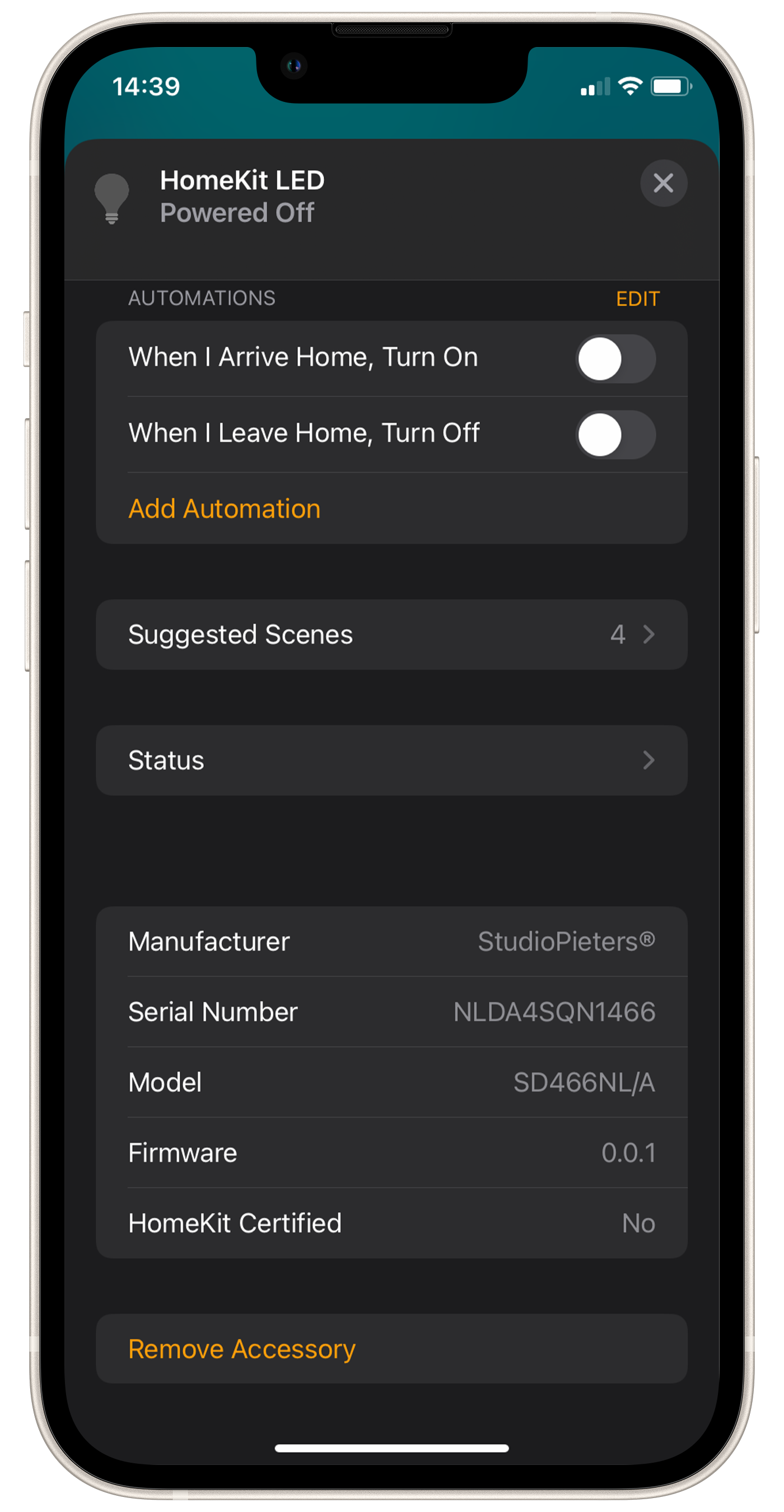
When HomeKit is ready you will see the HomeKit LED button in your screen, You can now turn your LED on and off. When you Look at the Settings, you see all the information about your newly build device. You can also add an automatization to your HomeKit LED if you want to.
 |  |  |
Testing the Hardware
Keep following my blog for more awesome ESP32 HomeKit accessories!