A few weeks ago I was looking for a small oscilloscope module. While searching the web I came across the type DSO138 from the company JYE Tech. The bandwidth of 200 kHz and the maximum sample frequency of 1 MHz were sufficient for my application. Because these modules are so very cheap for barely € 15,– with direct delivery from China, so I ordered one.

DSO138
Here you see the DSO138 module, it is a print on which, in addition to all soldered operating elements such as slide switches, push buttons and sockets for signals and power, a colour LCD is also attached.
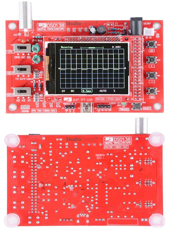
It can be seen on the left that the selection of the input coupling and the amplitude adjustment is realised with the simplest mechanical slide switches. The other functions are controlled with the push buttons on the right.
The RGB-LC display has a resolution of 320 x 240 (QVGA) with a screen diagonal of 2.4″ (6.1 cm). Since many a simple, but more expensive, scope has the same resolving power with a much larger display format, this seemed more than sufficient for my application. By the way, the scheme is included, which is not too bad, because that is no longer common with all measuring devices. This made it very easy to realise an external trigger input for TTL levels. The power supply comes from a 9V voltage source; from which approximately 100 mA is drawn. A simple voltage inverter creates the negative supply voltage, which, like the positive voltage rail, is stabilised with a linear regulator. The µC, an ARM-Cortex-A3 from ST with the type number STM32F103C8, is powered with 3.3 V with a separate voltage regulator.

The fast ADC used is also in the µC. It has a resolution of 12 bit and an input voltage range of 0 … 3.3 V. The centre of that range, 1.65 V, corresponds to the zero line on the display. The screen can be fully outputted with a sine wave signal of a considerably smaller amplitude. This probably serves, in combination with the high resolution of 12 bit, to make the offset of the input signal adjustable. This is because the offset is not compensated in the analog amplifier circuit, as usual, but is subtracted arithmetically from the data.
The relatively small used part of the input voltage range of the ADC’s does, however, lead to obvious spike disturbances, which occurred at many times of the horizontal deflection. They also did not disappear due to my attempts to block better in various places. Despite the always valid rule for price / quality ratio: “You get what you pay for” applies to this DSO module, that we get a relatively large amount of electronics for little money. And so we have to learn to live with some minor shortcomings. Incidentally, the DSO138 is not only available as a ready-to-use module: those who like to solder can also purchase it as a kit for a somewhat lower price, with the SMD components already assembled.
Learn How To Use An Oscilloscope
Are you frustrated by the complexity of the oscilloscope? Are you finding it hard to understand the basics and use this amazing test instrument? We have found the resources in this page for you. Learn how to use an oscilloscope with our series of tutorials and courses for beginners.