
Guide
DRV8825 Pinout
The complete pin reference for the DRV8825 stepper motor driver: 16 pins, up to 1/32 microstepping, and the exact wiring you need to drive a motor safely.
Overview
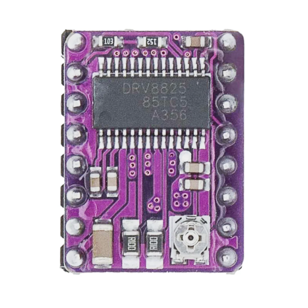
The DRV8825 is a stepper motor driver IC from Texas Instruments, widely used on 3D printers, CNC machines and robotics through breakout boards like the one made by Pololu. It’s not a programmable chip like the boards elsewhere in these guides, it’s a driver: a microcontroller sends it STEP and DIR pulses, and it handles the high-current motor coil switching.
Wiring
Set the current limit before connecting a motor, an unset or too-high current limit is the most common way to damage both the driver and the motor.
Pinout diagram
The 16-pin layout of the standard DRV8825 breakout module.

Dimensions
The standard Pololu-style DRV8825 breakout: 15.5 by 20.4 mm, with the current-limiting potentiometer near one edge.

Pin reference
All 16 pins, split across both sides of the breakout.
| Pin | Name | Function |
|---|---|---|
| 1 | GND | Logic ground |
| 2 | VMA | Motor power supply A (8.2V to 45V) |
| 3 | 2B | Motor coil B (output 2B) |
| 4 | 2A | Motor coil B (output 2A) |
| 5 | 1A | Motor coil A (output 1A) |
| 6 | 1B | Motor coil A (output 1B) |
| 7 | GND | Motor ground |
| 8 | VMOT | Motor power supply (same as VMA) |
| 9 | DIR | Direction input, sets motor rotation direction |
| 10 | STEP | Step input, advances the motor by one step |
| 11 | SLEEP | Sleep mode, active high, LOW disables the driver |
| 12 | RESET | Reset input, active low, resets internal logic |
| 13 | MS1 | Microstepping selection bit 1 |
| 14 | MS2 | Microstepping selection bit 2 |
| 15 | MS3 | Microstepping selection bit 3 |
| 16 | EN | Enable input, active low, enables motor outputs |
Microstepping configuration
MS1, MS2 and MS3 are usually tied HIGH or LOW with jumpers, not driven dynamically, though a microcontroller can control them live if needed.
| MS1 | MS2 | MS3 | Microstepping mode |
|---|---|---|---|
| Low | Low | Low | Full step |
| High | Low | Low | Half step |
| Low | High | Low | 1/4 step |
| High | High | Low | 1/8 step |
| Low | Low | High | 1/16 step |
| High | Low | High | 1/32 step |
Safety notes
Before you wire anything up
- Never connect or disconnect the motor while the driver is powered, the resulting voltage spike can destroy it.
- Set the current limit (VREF) before running the motor, an unset limit defaults to the maximum and can overheat both the driver and the motor.
- Add a heatsink if you plan to run near the 2.5A per-coil maximum, the bare chip throttles current well below that.
- STEP and DIR are logic inputs, both 3.3V and 5V microcontrollers work, but check your specific breakout board’s datasheet for its exact logic threshold.
Related
 Reference
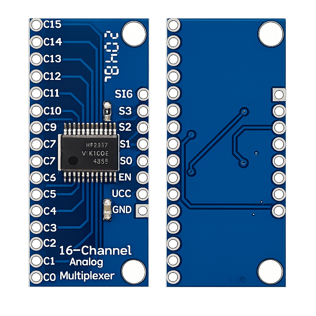
CD74HC4067 16-Channel Analog Multiplexer – Complete Guide
A 16-position analog switch controlled by just 4 GPIO pins, turning one ADC input into sixteen. This guide covers the pinout, channel-select truth table, ESP32 wiring, ESP-IDF/Arduino code, and how it compares to the 74HC4051 and the ADS1115.
Read more
Reference
CD74HC4067 16-Channel Analog Multiplexer – Complete Guide
A 16-position analog switch controlled by just 4 GPIO pins, turning one ADC input into sixteen. This guide covers the pinout, channel-select truth table, ESP32 wiring, ESP-IDF/Arduino code, and how it compares to the 74HC4051 and the ADS1115.
Read more
 Reference
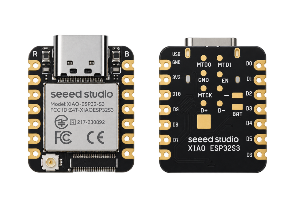
Seeed Studio XIAO ESP32S3 Pinout
The real pin reference for Seeed Studio's XIAO ESP32S3: thumbnail-sized, native USB, with a camera/display connector on the Sense variant.
Read more
Reference
Seeed Studio XIAO ESP32S3 Pinout
The real pin reference for Seeed Studio's XIAO ESP32S3: thumbnail-sized, native USB, with a camera/display connector on the Sense variant.
Read more
 Reference
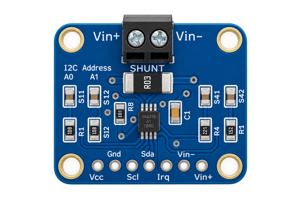
INA219 / INA226 Voltage, Current and Power Sensor Complete Guide
The INA219 and INA226 measure voltage, current and power on a low-voltage DC bus over I2C, using a shunt resistor and Ohm's law, not the mains-AC energy-meter ICs this site already covers. This guide covers both chips' real specs, wiring one to an ESP32, and which to pick for a battery or power-budget project.
Read more
Reference
INA219 / INA226 Voltage, Current and Power Sensor Complete Guide
The INA219 and INA226 measure voltage, current and power on a low-voltage DC bus over I2C, using a shunt resistor and Ohm's law, not the mains-AC energy-meter ICs this site already covers. This guide covers both chips' real specs, wiring one to an ESP32, and which to pick for a battery or power-budget project.
Read more
More guides
Keep building.
From ESP32 HomeKit accessories to Arduino and ATtiny reference guides, there’s more where this came from.
All guides