Zener diodes are a special type of semiconductor diode devices that allow current to flow in only one direction and also allow current to flow in the opposite direction, but only when exposed to sufficient voltage. And while that sounds a bit esoteric, they’re actually some of the most useful components to ever cross an engineer’s bench, providing great solutions to some common circuit design needs.
In what follows, we’ll show you how (and when) to use a Zener for applications such as simple reference voltages, clamping signals to specific voltage ranges, and easing the load on a voltage regulator. The name Zener diode is named after the American physicist Clarence Melvin Zener, who discovered the Zener effect.

To understand how Zener diodes differ from other diodes, let’s first consider the properties of ordinary diodes. And while there are many different types of diodes – see here for a long list – let’s focus on so-called “normal” semiconductor diodes, usually built with a pn silicon junction.
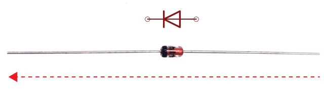
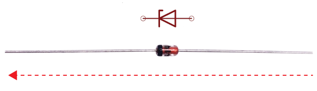
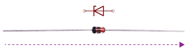
Diodes usually come in cylindrical glass or plastic packaging, marked with a stripe on one side to indicate polarity. In a perfectly ideal diode, the current flows in only one direction, from the anode (positive side) to the cathode (negative side) which is marked with the bar. The schematic symbol is a triangle pointing to a bar, where the current flows in the same direction, to the dashed (striped) end. Surface-mounted versions of diodes tend to follow the same labelling convention, with the cathode end marked with a wide stripe.
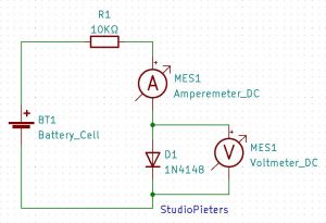
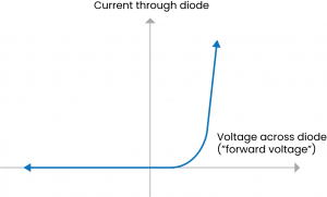
If we connect a diode in a simple circuit with a variable voltage source and a current-limiting resistor, we can measure the current I through the diode when a certain voltage V is applied across it. For an ideal diode, no current flows at all when the voltage is less than zero: the diode completely prevents the flow of reverse current. For small positive voltage (“forward bias” or sometimes “forward voltage”), a small amount of current can flow and a very large amount of current above a certain threshold. The amount of current flowing is actually exponential with increasing voltage.

Threshold at which a significant amount of current is usually around 0.7 V for simple semiconductor diodes, but can be as low as 0.15 V for Schottky diodes, or as high as 4 V for certain types of LEDs.
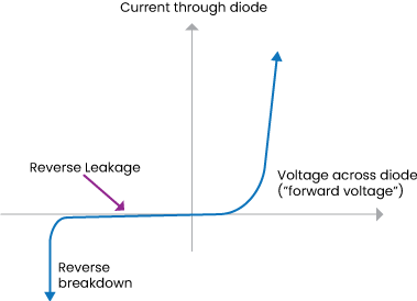
Of course, no diode is really ideal. In real diodes, when the voltage is reversed, a very small amount of current (leakage) can flow. And, most importantly, each diode is rated for a certain maximum amount of reverse voltage. If you apply a voltage more negative than that limit, the diode undergoes a “reverse breakdown” and begins to conduct a significant amount of current, but backwards from the normal direction of the diode current. For an ordinary diode, we would say that the diode is faulty if it starts to conduct current in that direction.

As an aside, the actual physics of what happens in a failure is quite interesting; two separate effects, the Zener effect and Avalanche breakdown, both contribute to this behaviour.
Zener diodes
Zener diodes are semiconductor diodes manufactured to allow their reverse breakdown to occur at a specific, well-defined voltage (the “Zener voltage”), and are designed to be operated continuously in that breakdown mode. Commercially available Zener diodes are available with breakdown voltages (“Zener voltages”) from 1.8 to 200 V.
The schematic symbol for a Zener diode is shown above – it is very similar to that of an ordinary diode, but with curved edges on the bar. The Zener still conducts electricity in the forward direction like any other diode, but also conducts in the reverse direction, if the applied voltage is reversed and greater than the Zener breakdown voltage.
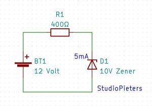
Power supply. The resistance value is chosen so that several mA flows through and through the Zener, keeping it in the breakdown region. In the above circuit, there is 10 V across the Zener diode and 2 V across the resistor. With 2 V across a 400 ohm resistor, the current through that resistor (and the diode, in series) is 5 mA.
Zener voltage references
The fixed voltage property of Zener diodes makes them extremely handy as quick voltage references. The basic circuit looks like this:
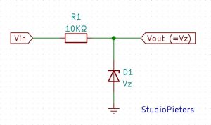
There are a few requirements to consider. First, the input voltage must be higher than the Zener voltage. Second, the resistance value should be chosen so that current always flows through the Zener.

Some caveats: This isn’t necessarily a good all-purpose power supply – the resistor limits how much current can be drawn. It is also not necessarily an accurate voltage reference; the voltage will depend on the amount of current being drawn. (That is, to keep the voltage stable, the load driven by that reference voltage must be consistent.) The voltage also depends on temperature. Zener in the 5-6 V range have the best temperature stability, and there are high precision Zener diodes (like the LM399) that contain their own temperature stabilized furnace to further keep the diode temperature as stable as possible.
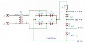
If you take this idea a little further, you can actually build a full multi-rail power supply using nothing more exotic than a set of Zener diodes to generate all the necessary voltages, provided the current requirements are modest for the various supply voltages. The above circuit is part of a working laboratory instrument.
Voltage clamps: Limiting signals with Zener diodes
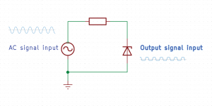
A varying analogue signal can be limited to a fairly narrow range of voltages with a single Zener diode. If you have a voltage that fluctuates between +7V and –7V, you can use a single 4V Zener, connected to ground, to make sure the signal doesn’t go above 4V or go below -0.7 V (where the diode conducts). Forward to the ground.

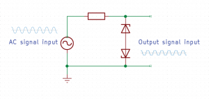
If you want to limit the signal to never go negative, for example for input to an analogue to digital converter that accepts signals in the 0 – 5 V range, you can connect the anode of the Zener diode to a power rail at 1 V, in instead of ground. Then the range of the output signal would be limited to the range of 0.3V – 5V.
Another handy trick is to use two Zener diodes, oriented oppositely, in series. For example, this can provide a symmetrical limit for the deflection of a signal from the ground. This is also a common configuration for using Zener diodes as transient suppressors.
Voltage translation: Easing the load on a regulator
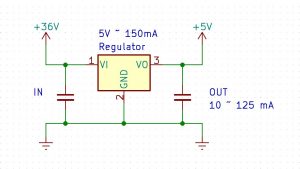
Here’s something that doesn’t work. We have LM7805, which is a linear regulator type with 5V output, which can provide up to 150mA output, and its load will be variable. We need to run it from a 36 V source. Unfortunately, the maximum input voltage of the LM7805 is 26 V.
Let’s try adding a resistor in series to drop some of that voltage:
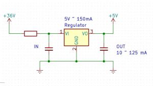
Our output load can be as high as 125 mA and as low as 10 mA. So, what value resistor will work for us?
Suppose we assume a load of 125 mA. Then to pick up (say) 20 V on the resistor, 20 V / 0.125 A = 160 Ohms. If we use 160 ohms, that drops only 160 ohms × 0.01 A = 1.6 V at 10 mA load, and 36 V – 1.6 V is still greater than 26 V. Just to be safe with the 10 mA load, we must choose a resistor that gives us at least a drop of 11 V, for 25 V input to the regulator. So 11 V / 0.01 A = 1100 Ohms would be safe for the 10 mA load. But if the load increases to 125 mA, the drop over 1100 Ohm would be V = 0.125 A × 1100 Ohm = 137 V, meaning the input to the regulator would be below 5 V and stops
Clearly, there is no resistor value that you can pick that actually will work for both the low and high current cases.

As an aside, we’ve skipped a few minor details about voltage regulators that often deserve attention. First, a linear regulator always requires slightly more voltage on its input than its output. This voltage difference is called a “dropout voltage” and can be as high as 0.6 V for the LM7805, a so-called “low dropout” regulator. This means that when outputting 5 V at 150 mA, the controller input terminal must be at 5.6 V or higher. We can safely ignore this, because 36 V – 137 V is still below 5.6 V.
A second minor detail is that a linear regulator actually draws slightly more current into its input than it draws from its output. The reason for this is that some of the current flowing to the regulator’s input flows to ground through the third “ground” terminal, rather than to the output terminal. This “quiescent current” can be up to 12 mA for the LM7805. This means that when 125 mA flows from the output terminal of the controller, as much as 137 mA can flow into the input terminal. In the example above, this means that the maximum voltage drop across a 1100 ohm resistor is more accurately estimated at V = 0.137 A × 1100 Ohm = 151 V. Again, this doesn’t change our analysis.
Let’s try again, this time with our friend, the Zener diode.
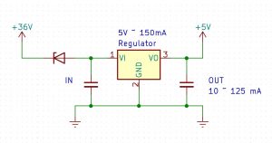
Finally, let’s try using a fat 20 V Zener diode (type 1N5357BRLG) to reduce some of the load. Then the output on the Zener’s anode is only 16 V, well within the safe input range of the controller. The 1N5357BRLG is rated for up to 5W.
When the controller operates on 125mA output, the input current can go up to 137mA including quiescent current, so the power dissipated by the Zener can go up to 20V × 0.137A = 2.74W. It gets hot, but we’re good at the safe operating conditions of the Zener, and now the circuit will work.

Reference
Digikey, Zener Diode: Basic Operation and Applications, https://www.digikey.com/en/maker/blogs/zener-diode-basic-operation-and-applications Evilmadscientist, Basics: Introduction to Zener Diodes, https://www.evilmadscientist.com/2012/basics-introduction-to-zener-diodes