In this blog, I’ll show you how to add a battery and charger to any microcontroller based project based on an Arduino, ESP8266, ESP32, or any other microcontroller. This in a correct, safe, easy and cheap way.
This project is not just about building it, but also highlighting a few things, very important for makers who want to power their gadgets with batteries. The uses are endless and while I will use my project of an ESP32 HomeKit Alarm System as an example, you can use it in any other project.
Adding a battery
This blog isn’t just about telling you how to “connect” the battery, but teaching you why it’s important to do it a certain way, and that’s why it’s so comprehensive. I think everyone knows by now that Lithium-ion (Li-Ion) and Lithium Polymer (Lithium Polymer) batteries, or “Lipo“, are fragile and can even be dangerous. Many of you probably remember the scooters that were left burning on the street not so long ago.

We live with these batteries and usually nothing happens, but that’s because the vast majority of commercial devices they are used in know their risks, and they manage the batteries properly. However, the danger does not come from the battery itself (well, a bit) but mainly from its use.
We want the battery of our meter to be always charged, we want our device to work while the battery is charging. We don’t want to have to turn the meter off for a few hours while the battery charges.
The Commandments of Li-ion and Li-po Batteries
These are the main commandments for working with Li-ion and Li-po batteries:
– Do not overcharge the battery
– Do not short-circuit the battery
– Do not over-discharge the battery below a certain level
– Don’t let it be hot Battery
– Do not put batteries in parallel if they are not the same and have the same charge

These aren’t the only rules, but they are the most important to keep your house from burning.
The Mistake in most projects
Most DIY projects seen on the internet make some mistakes. I’m going to try to explain this to you in a simple way. Above you see in red “Do not overcharge the battery“. This means that while the battery is charging, there is a certain point where you should stop charging and go no further from there. Continuing to charge the battery afterwards is dangerous.
As you can imagine, it has become clear from the previous section that the charging process of a battery is very delicate and that the chargers for Li-ion and Li-po batteries are very precise devices. Unlike lead acid, nickel cadmium or nickel metal batteries, which can withstand a little more abuse.
I’m not going to explain in detail what the charging process of a Li-ion and Li-po battery is like, but I’m going to try to explain to you the main points of what a charger does:
- First, the charger performs some safety checks to make sure the battery is not connected backwards and the battery is within a certain voltage range, etc.
- The charger then performs a “preconditioning” where in a very controlled manner and by delivering low currents it checks that the battery is “absorbing” the current it is expected to absorb and the voltage of the battery rises by applying current to it.
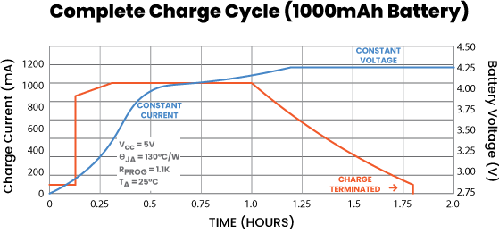
- Starts charging with constant current, which takes almost the entire charging process. This means that the charger will change the voltage feeding the battery as needed, so that the battery always absorbs the same intensity.
- When the charger detects that the battery is close to 4.2 volts, which indicates the maximum voltage, it will begin to reduce the current supplied to the battery.
- When the current is lower than a certain value, the charger will stop charging. The charging process is finished.

The problem in most projects is that the last point is never reached, and the battery charges and charges and charges as long as the battery lasts.
The Hardware
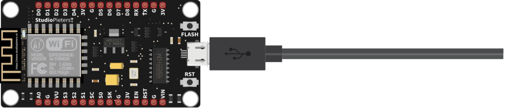
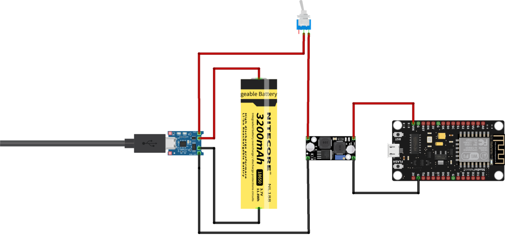
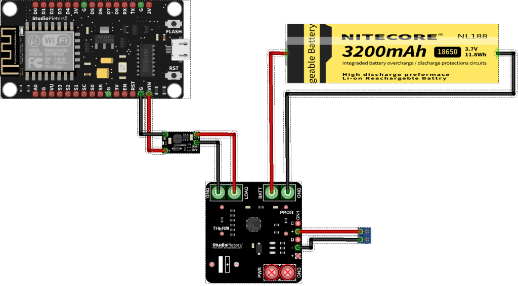
Let’s start with a project. Here we use a Standard ESP8266 NODE MCU, which is normally powered at 5 volts.
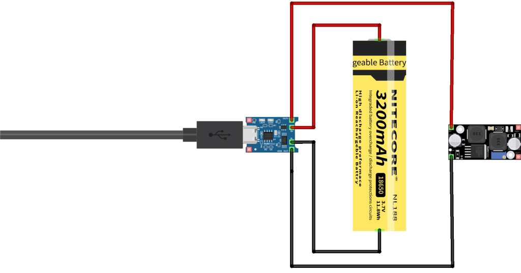
The next step would be to add a battery with a charger module. A TP4056 and capable of charging the battery with an accuracy of 1.5%. The TP4056 can always be connected, and the battery is permanently charged.
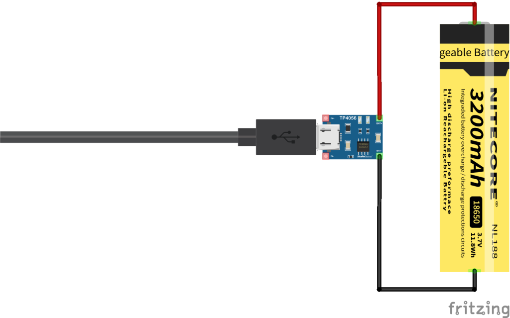
In the previous example, we would have a charged battery, but that battery would give us a voltage between about 3 and 4.2 volts, depending on how the battery is charged. We wouldn’t be able to use the battery directly to power our circuit. Because it takes 3.3V or 5V to run the module.
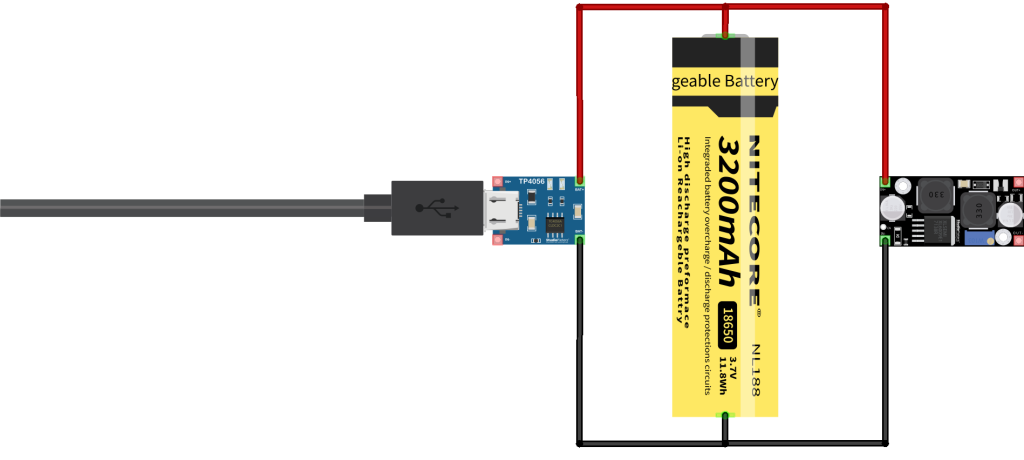
One way to solve this problem is to connect a circuit in parallel to the battery called a “step up down” module. On the Module, we can put any voltage on the input between 2.5V and 30V. The output will always give us a stable 3.3V or 5V volts.
When, after a short while, the battery is empty or something else happens. You will find that things are missing to make the circuit work correctly and, perhaps more importantly, to be able to sleep peacefully at night.

For example, a protection against over discharge, because if you leave your device connected for too long and the battery discharges below a point, most batteries will die, some batteries have this protection built in.
Another example is short circuit protection, because let’s be serious, a short circuit can occur at any time for any reason.
So you go back to your project and change the simple charger you had been using for a more complete charger, which includes the necessary safeguards. Note the connections on the charger, they are very similar but not the same, the previous one only had two terminals for output and this model has four independent terminals, two for the battery and two more for output.
At the moment, our project has a power system that works with a battery. The battery can be charged and at the same time supplied the device with the necessary protections…. Or does it?
But this design, which is still fairly widespread and in use by many projects, hides a problem, one that can put you at risk.
THE CHARGER IS NEVER FINISHED TO CHARGE THE BATTERY, See The Commandments of Li-ion and Li-po Batteries here above!
If we take circuit datasheet of the TP4056 integrated circuit, we can read the following:
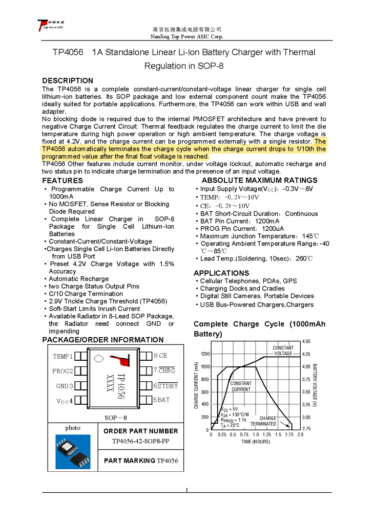
“The TP4056 automatically terminates the charge cycle when the charge current drops to 1/10th the programmed value after the final float voltage is reached.”
This means that the TP4056 will not stop charging the battery until the final voltage has reached 4.2 V and the charging current drops to one tenth of the programmed charging current.
By default, most boards with the TP4056 are programmed for a charging current of 1 Ampere. It can be changed by changing a resistor. This means that until there is a consumption less than 100mA, the charging process will not be interrupted! Since we have connected an extra circuit, the charger will never stop charging the battery due to that extra consumption. If the TP4056 programmed for a charging current of 500 Millie Ampere. Then that means until there is a consumption less than 50mA, the charging process will not be interrupted!
The solution
The solution to the problem described above is to make sure that the battery charging and the power circuits of our device are independent of each other.

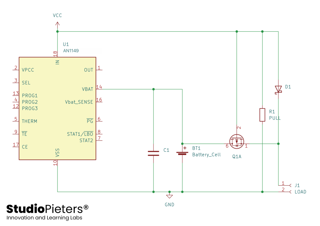
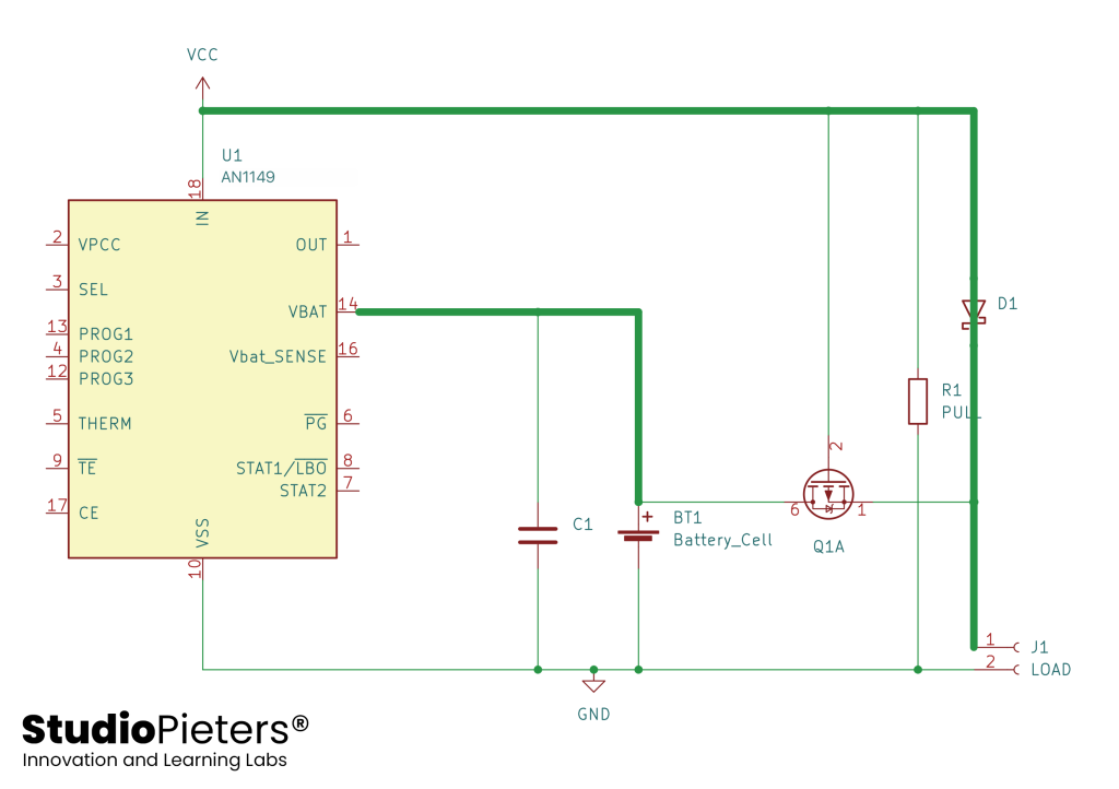
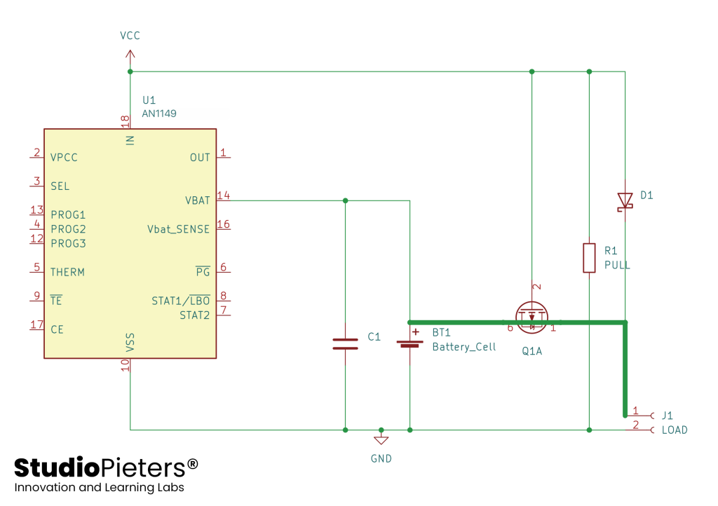
Look at the diagram below, imagine we add a switch in our circuit, and it changed automatically depending on whether the external power is connected or not.
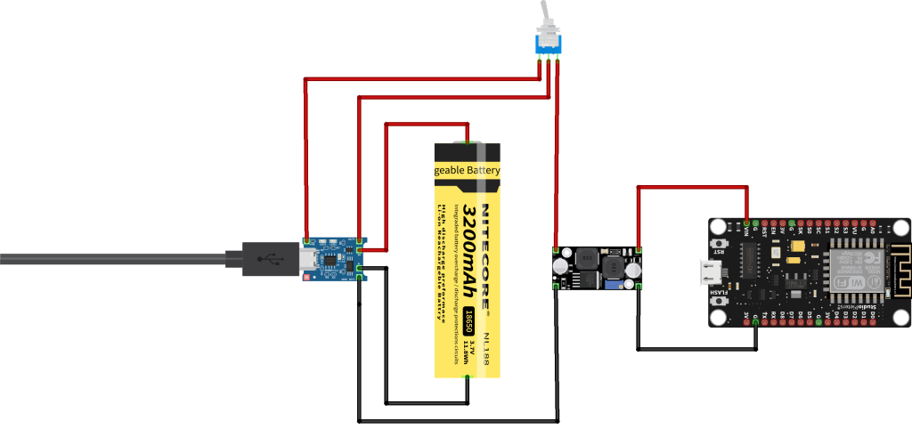
Here we connected it with the external power supply. As you can see, the battery continues to charge, but has no connection to our circuit
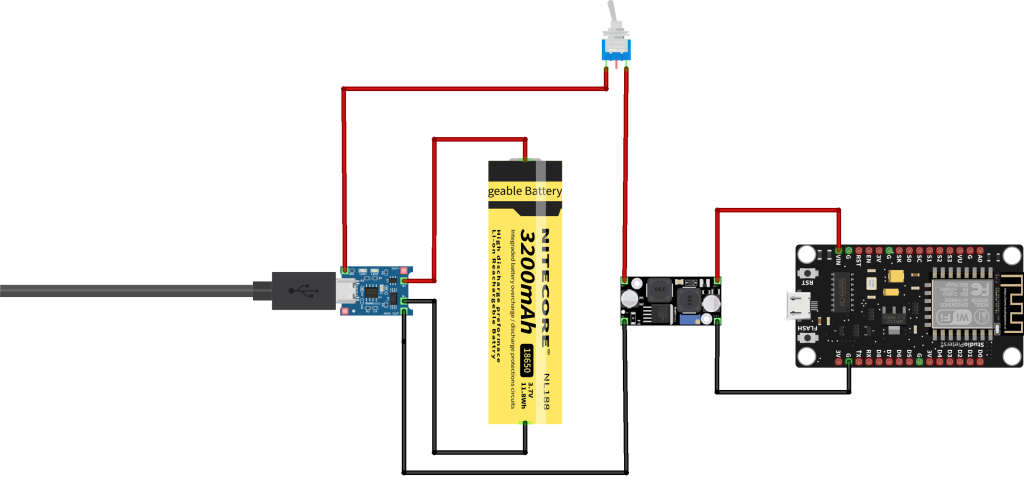
And here we have it connected to the battery
This, electronically, is usually done by a MOS FET transistor and a diode, working together so that between the two they are able to direct current in the correct path depending on whether there is an external power supply or not.
Circuit
Basically we have the same dangerous circuit as before, but now we have that “automatic switch” that chooses the correct path for the current.
The following is the path the current takes when external power is connected. As you can see, the battery charge and the power supply of our device are completely independent of each other.
If there is no external power supply, our device will only be powered by the battery
In this way, we also give priority to external power to the battery when the device is powered by the cable, in this way our circuit avoids continuously charging and discharging the battery, which will shorten its life significantly.

The images above are from Microchip’s application note. Which talks about the design of Li-Ion battery chargers and the “load sharing” or “power path” circuits. If you want to know more, I recommend you read it here.
Doing it the right way
A few years ago, we would have needed a lot of components. Different for battery protection, different for charger, different for “load sharing“. Today, there are integrated circuits on the market that perform all of these functions in a quarter of a square centimetre.

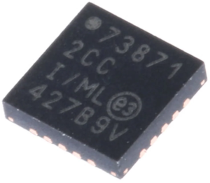
MCP73871
The MCP73871-2CCI/ML is a stand-alone system load sharing and Li-ion/Li-polymer battery charge Management Controller with AC-DC wall adapter and USB port power sources selection. It is also capable of autonomous power source selection between input or battery. This device automatically obtains power for the system load from a single-cell Li-Ion battery or an input power source (AC-DC wall adapter or USB port). This device specifically adheres to the current drawn limits governed by the USB specification. With an AC-DC wall adapter providing power to the system, an external resistor sets the magnitude of 1A maximum charge current while supporting up to 1.8A total current for system load and battery charge current. This device employs a constant current/constant voltage (CC/CV) charge algorithm with selectable charge termination point.
- Integrated pass transistors
- Integrated current sense
- Integrated reverse discharge protection
- ±0.5% Regulation tolerance
- Maximum 1.8A total input current control
- Resistor programmable termination set point
- Automatic recharge
- Automatic end-of-charge control
- Safety timer with timer enable/disable control
- 0.1C Preconditioning for deeply depleted cells
- Battery cell temperature monitor
- Charge status and fault condition indicators
The datasheet of the MCP73871 can be found here.
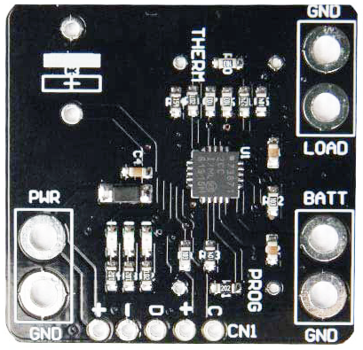
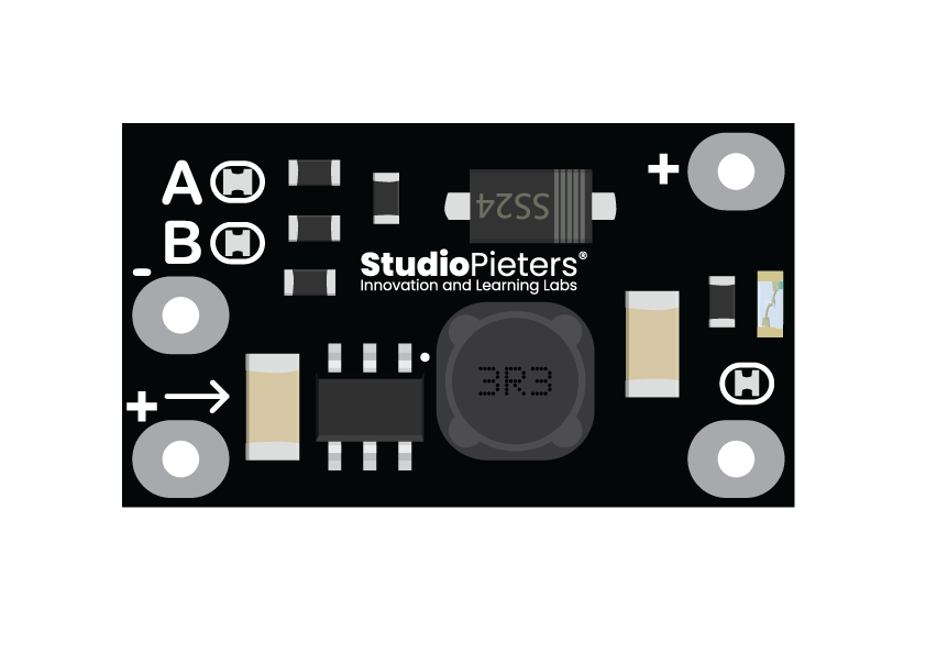
Because the MCP73871-2CCI/ML is so small, it is actually very difficult for an average maker to solder correctly. The good news is that we can buy a board that integrates the MCP73871. The project is therefore also easier to realize.
This circuit is also fully compatible with the charging of batteries by solar panels of 5.5V and 6V. Because the MCP73871 module has certain intelligence that is necessary not to overload the solar panel, and it is always possible to extract the maximum energy. Read more about this feature, called VPCC, below.

IMPORTANT
If you are going to use this board and power it, with a charger or power supply, then I recommend that you connect it as shown below. Connect the voltage to the + and – points instead of the PWR terminal, look closely at the picture so as not to confuse the two pins marked “+” which are quite close to each other.
Functionalities of the battery power system
There are other ways to approach this problem, but the one I propose in this tutorial has a lot of advantages. These are some of them:
- Integrated system charge sharing and battery charge management (load sharing / power path).
- Simultaneous system power and load lithium-ion battery
- The voltage proportional current control proportional (VPCC) ensures system charging takes priority over lithium-ion battery charging current
- Management of low loss power path with “ideal diode” operation
- Controller full linear load management.
- Integrated power path transistors
- Integrated reverse discharge protection.
- Selectable input power supplies: USB port or wall adapter AC DC
You also have multiple additional options (for some of them you will have to check the datasheet of the integrated circuit to know how to use them):
Preset High Precision Charge Voltage Options:
- Battery charging at 4.10V, 4.20V, 4.35V or 4.40V
- Regulation tolerance of 0.5%.
- Constant current / Constant voltage (CC / CV)
- 1.8A maximum total input current control (with heat sink). Without a heat sink, it is recommended not to exceed 1Amp.
- Programmable fast charge current by resistance. Control: 50 mA to 1A
- Resistor programmable load termination set point
- Selectable USB input current control. Absolute maximum: 100 mA (L) / 500 mA (H)
- Automatic recharge
- Automatic end-of-charge control
- Safety timer with timer on / off control
- 0.1C preconditioning for heavily depleted cells
- Battery cell temperature monitoring
- Low voltage blocking (UVLO)
- Low Battery Status Indicator (LBO)
- Power Status Indicator (PG)
- Indicators of charge status and error states

Some pins of the MCP73871
The MCP73871 IC has several pins that, depending on whether they are set to high or low logic level, change the operating characteristics of the chip, activate and deactivate options, etc. In the datasheet, you can find the detailed description of what each of them does.
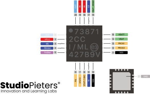
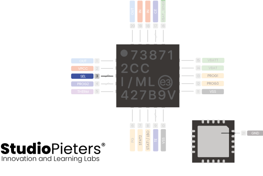
SEL pin (3) – Operation from USB port or power supply
This pin allows the MCP73871 to operate in two modes, ‘USB‘ or ‘Power‘.
When set to low level the operating mode is USB and, in this mode, the MCP73871 will limit current consumption so as not to damage the USB port to which it is connected (according to the USB standard these ports have relatively low power limitations).
With pin set to high level, the operating mode will be “power adapter”. In this case, the MCP73871 eliminates the limitations of input current consumption and will consume up to 1.8A from the power supply to which it is connected.
This board comes by default with this pin set to high level (through a 10K resistor) so its operation mode is with power adapter, being able to consume up to 1.8A. The board has at the bottom a pad marked SEL that allows to modify this pin level easily (easily when knowing how to use it, of course. I still have to investigate the schematics).
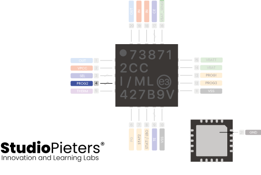
Pin PROG2 (4) – Maximum current of the USB port when SEL = LOW
This pin allows, when the MCP73871 is operating in USB mode (SEL pin at low level), to choose if we want the chip to consume up to a maximum of 100mA or 500mA (low level = 100mA, high level = 500 mA). This pin is accessible from the bottom of the board, on a pad marked PROG2.
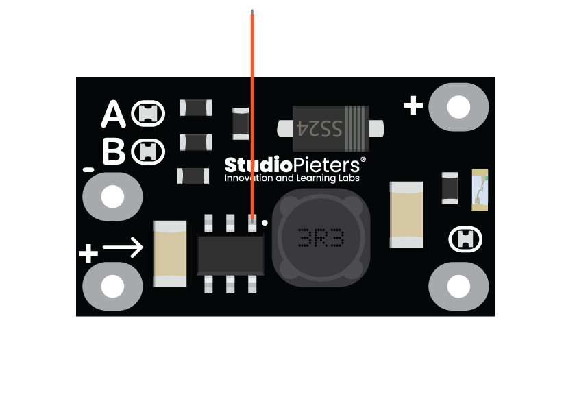
Pin PROG1 (13) – Load current programming
The battery charging current can be programmed by means of the resistor connected to the PROG1 pin of the MCP73871 IC, in this way it is possible to adjust it between 100mA and 1000mA.
The board is supplied from the manufacturer with a 2K resistor, which programs the MCP73871 to charge the battery with 500mA. Substituting the 2K resistor with a 1K resistance we would get a load current of 1000mA, and if we change it to a 10K one, the charge current would be limited to 100mA.
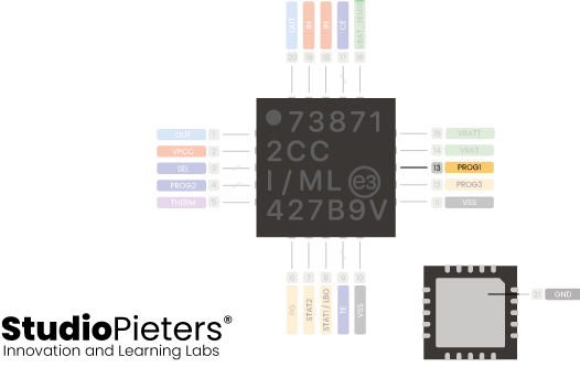
Keep in mind that the maximum charge current indicated by the battery manufacturer must always be respected. When this data is not available, the acceptable value would be half the battery capacity (That is, if the battery is 1200mAh it is usually acceptable to charge it at 600mA).

VPCC pin (2) – Voltage proportional charge control (important for solar panels)
This pin is important for the operation of the MCP73871, since one of the main characteristics of this chip depends on it, which differentiates it from other similar chips.
The MCP73871 allows the battery to be charged using solar panels (maximizing its efficiency to take full advantage of the energy that these panels can provide), and one of the characteristics of the panels is that as you charge more of the solar panel (asking for more intensity of exit) there is a critical point at which the panel “collapses”; its voltage drops sharply and the energy it can deliver as well.
This means that we have to be careful so that the panel does not collapse. In other words: you have to try to get the maximum intensity possible from it, but just before the point of “collapse” and that point is continuously varying with the solar energy that exists at that moment and with the consumption of the circuit that we have connected.
The VPCC feature that includes the MCP73871 chip serves to optimize this and works as follows (short and simple explanation, so you understand what it is about, to find out more see the datasheet where this functionality is explained in detail):
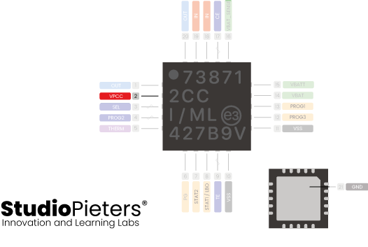
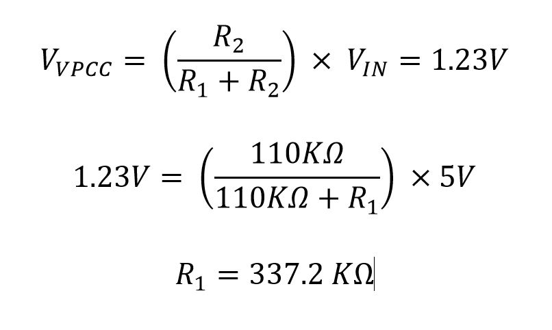
The MCP73871 monitors the voltage delivered by the panel through a voltage divider that connects to the VPCC pin. The voltage divider must be calculated so that the VPCC pin has 1.23V when the voltage of the solar panel is the optimum one that allows it to give maximum energy.
When the voltage at the VPCC pin drops below 1.23V the chip reduces the intensity demanded from the panel, lowering the charging current to give priority to the device connected to its output (and supplying the intensity that is necessary from the battery, if that of the solar panel is not enough, until complete).

This function can be deactivated, joining the VPCC pin to IN.
For example, if we have a system designed for panels that provide 5.5V with ± 0.5V tolerance (which is quite common), we will have to select the worst scenario, which in this case would be 5.0V, to calculate the voltage that we must apply to the VPCC pin across the voltage divider.
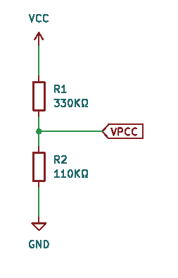
This voltage divider that you can see in the example is very similar to the one that our board has mounted from the factory. The difference is that instead of a 330K resistor we have a 270K resistor and instead of a 110K resistor we have a 100K resistor.
The board we have chosen is factory configured to optimize operation as a charger with a solar panel, and not with a power supply or USB port.
As our board is factory optimized for use with solar panels with a voltage of 5.0V, it is possible that, if we connect it to a USB charger or power adapter, the voltage drops below 5.0V (due to the voltage drop in the cables and the tolerances of the components) which would mean that the MCP73871 would limit the current that it would demand from the charger or power adapter, complementing the energy that is missing to power the circuit from the battery.
Important: If you are going to use this circuit with solar panels, and you are going to power 5V equipment Instead of a “step up”, it is recommended that you use a “step up down”, since solar panels can give up to 5.5 or 6V at full power. The “step up” only raises the voltage (so the input voltage must be lower than the output voltage), while the “step up down” is capable of raising or lowering it, depending on whether the input voltage is lower. Or higher than desired.
Modifying the board for use with a USB charger or power adapter (modify VPCC)
If we are going to regularly use our charging board powered by a charger or power supply, (and although in many cases everything works correctly because the voltage remains above 5V) it is advisable to reduce the VPCC, modifying the voltage divider or disable it by means of connecting the VPCC pin to IN.
As I have mentioned in the previous point, the board, as it comes from the factory, is optimized for charging by solar panels, with the VPCC adjusted so that the charging current decreases when the power supply drops below 5V.
This, when using the board with a power supply or USB charger, is a lottery because depending on several factors that I have already mentioned, it is easy for the power supply to drop below 5V, so the charging current would be drastically reduced.
To solve this problem, you have two options:
- You can completely disable VPCC by binding the VPCC pin to IN.
- You can change the VPCC voltage divider to lower the voltage from which the load drops.

I am going to explain here how you can easily disable VPCC completely (option 1).
I am not going to explain option 2 step by step for two reasons: The first is that it is normally not necessary if you are going to use the board with a USB charger or power supply. The second is that, being an advanced use, it is assumed that you know what you are doing and in the previous point I have already explained how to calculate the voltage divider yourself.
Disabling the VPCC of the MCP73871
As I mentioned before, we can deactivate this functionality, joining the VPCC pin to Vin.
And that how do we do it?
Well, it’s simple: As I explained before, the VPCC pin is connected to the power input through a voltage divider as follows:
This voltage divider that you can see in the example is very similar to the one that our board has mounted from the factory. The difference is that instead of a 330K resistor we have a 270K resistor and instead of a 110K resistor we have a 100K resistor.

This is the position of the two resistors that interest us on our plate (R1 and R5 is the silkscreen that is on the plate, although now you will not see it well because the resistors are on top of the silkscreen, hiding it)
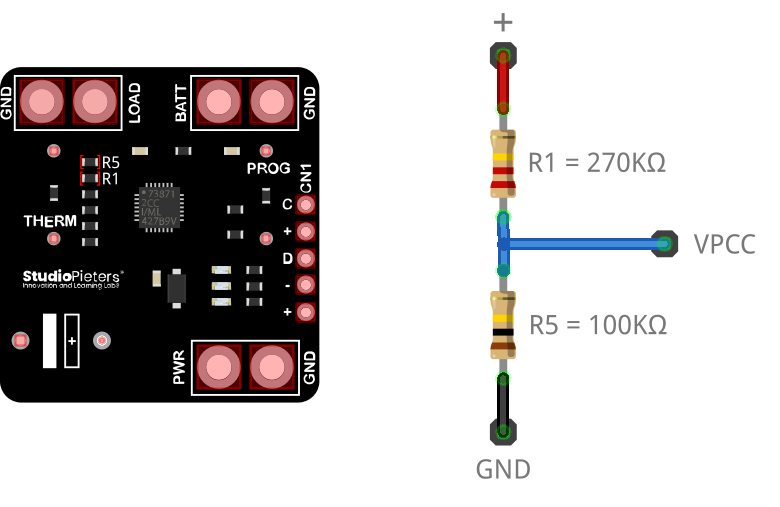
As what we have to do is to connect the VPCC pin directly to Vin, we only have to remove both resistors and in the place occupied by the 270K resistor we make a bridge with a drop of tin or a piece of wire (where the 100K resistor was). That’s it!
You have step-by-step instructions to make this modification in the second video, which you can find above.
The step-up and optimization of consumption
After much research, it appears that the step-up used, also called boost converter, is based on the integrated circuit MT3608 (or a Chinese version).
An interesting thing about this chip is that it has a ENABLE pin (enable), which allows you “Turn on and off” at will the step up from your microcontroller, and that way you can turn off and on the sensors or actuators that you have connected to it in order to save energy.
His operation it is very simple: when this pin is connected to VCC, the step-up is working and at its output we will obtain the expected voltage. When the pin is connected to GND, the chip will be “off” and at its output we will get 0 volts (which in practice means turning off whatever we have connected to it). This is essential for energy savings.

The step-up board does not have this pin accessible, and it comes from the factory permanently connected to VCC (so that the step-up is always working), so if you want to use this pin, you will have to perform a little modification, consisting of cutting the track that connects to VCC and connect the pin to a pin on your microcontroller, by means of a cable.

When the pin of your microcontroller is at level 1 (on) we will start the step-up and when it is at level 0 we will stop it.
It is a tricky operation, given the small size of the components, but, as I always say, nothing that cannot be achieved with a little determination.
In the following photographs, you can see the track of the printed circuit board that you have to cut to disconnect it from VCC, as well as the wire soldered to the ENABLE pin that you must connect to the pin of your microcontroller that you want the step-up to turn on and off.

REFERENCE
emariete, Adding battery charger to ESP8266 and ESP32 (well done), https://emariete.com/en/co2-meter-with-battery-well-done NanJing Top Power ASIC Corp, Datasheet, www.tp4056.com/d/tp4056.pdf Microchip, Datasheet, https://ww1.microchip.com/downloads/en/DeviceDoc/MCP73871-Data-Sheet-20002090E.pdf