Through some researches I did online on how to minimize components use, I stumbled with using an ATTiny13A chip to be used in the project. And through some more researching, I decided to have my new project done using the ATTiny13 Chip.

ATTiny13 Chip
I bought these chips from Ali-Express. First I need to study first the pin out of the ATTiny13A, and relate this to the ATTiny13A Chip The image below shows the pin out of the integrated circuit.
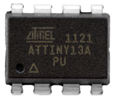
ATTiny13A Chip
I bought these chips from Ali-Express. First I need to study first the pin out of the ATTiny13A, and relate this to the ATTiny13A Chip The image below shows the pin out of the integrated circuit.
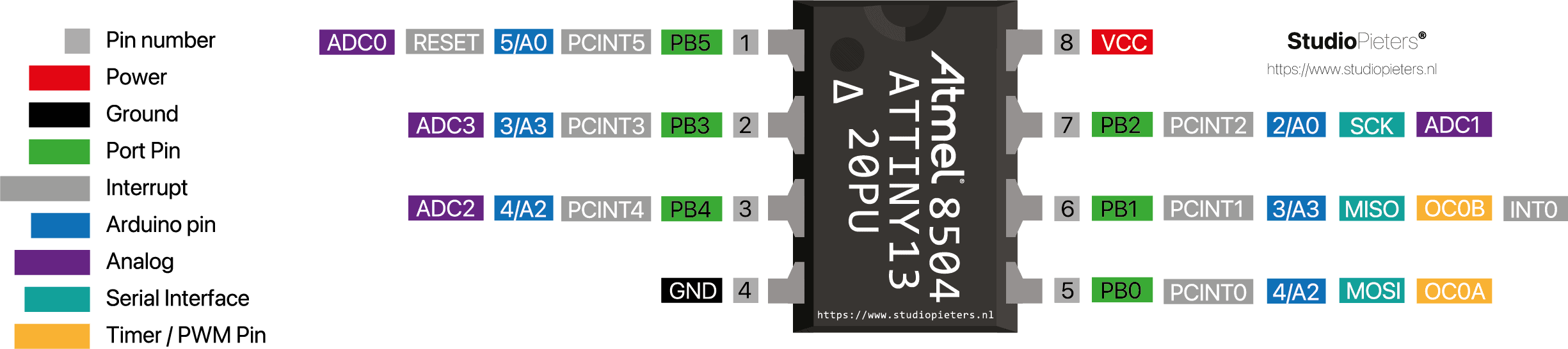
The notch at the top of the chip indicates where pin 1 is, then the count continues consecutively counter-clockwise. Now, let’s look at the ATtiny13A.
At the ATtiny13A IC diagram, we see the following pins labeled with PB0, PB1, PB2, PB3, PB4, and PB5. You will also see GND and VIN pins. These correspond to the Ground (Pin 4 of the IC), and Input Voltage (Pin 8 of the IC).
ARDUINO NANO TO ATtiny13A CONNECTIONS
Let’s connect the necessary pins together on both boards.
1 x Arduino Nano (or any Arduino board will do)
1 x ATtiny13A
6 x Jumper Wires
1 x Electrolytic Capacitor – 10µF ~ 25V
We need to connect the MOSI, MISO and SCK pins of both boards together (refer to the IC pin out), and Digital Pin 10 of the Arduino Nano to P5 of the ATtiny13A.
Connect the following (I am using an Arduino Nano, so you have to take note the necessary pins of the board you are using when using it as an
ISP).
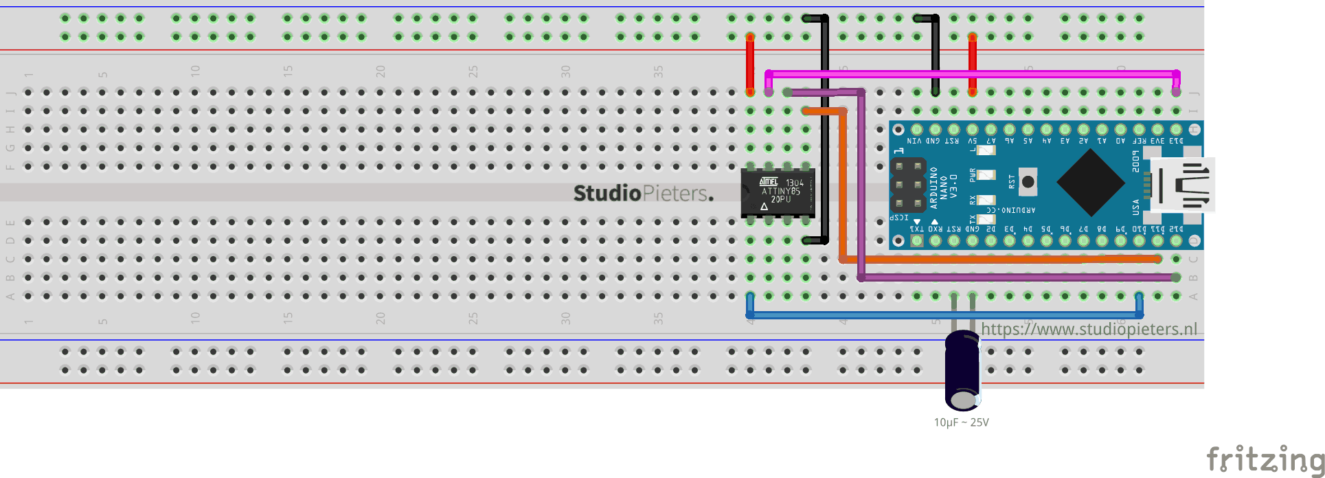
Add a 10uF capacitor between RESET and GND in Arduino. This is to avoid Arduino Nano from being auto reset when we upload the program to ATtiny13A. If you are using a electrolytic capacitor make sure the anode goes in GND of Arduino Nano.
| Arduino Nano | ATtiny13A | |
| MOSI | Digital Pin 11 | PB0 (Chip Pin 5) |
| MISO | Digital Pin 12 | PB1 (Chip Pin 6) |
| SCL | Digital Pin 13 | PB2 (Chip Pin 7) |
| RESET | Digital Pin 10 | PB5 (Chip Pin 1) |
| VCC | VCC (5V) | VCC (Chip Pin 8) |
| GND | GND | GND (Any GND pin) |
There are two things we need to set up to successfully program the ATtiny13A.
INSTALLING THE ATTINY BOARDS
Open the Arduino IDE Software then go to Arduino > Preferences. You will see Additional Boards Manager URLs. Add this link there, by pressing the rightmost icon. and ad this link:

https://mcudude.github.io/MicroCore/package_MCUdude_MicroCore_index.json
Press OK (then another OK to exit from Preferences).
Now, go to Tools > Board > Boards Manager. Type attiny in the search field, and you should see MicroCore. Click it (MicroCore by MCUDude) and install the board. Now, you should see attiny boards from the list when you go to Tool > Boards. Scroll down to verify that the board is indeed installed.
ARDUINO AS ISP
Attach the Arduino Nano to your computer. Go to File > Examples > ArduinoISP, and click on Arduino ISP. Then go to Tools > Boards and select Arduino Nano (or your preferred board). Go to Tools > Port and select the port where your board is connected to. Upload the ArduinoISP sketch to your Arduino Nano (or your preferred board) by going to Sketch > Upload. At this stage, your Arduino Nano is ready to be used as a programmer.
Note: In some cases you need to select Processor : “ATMega328P (Old Bootloader)”

UPLOADING SKETCH TO ATtiny13A DEVELOPMENT BOARD
Make sure that the connections are as stated as described here above. Open the program / sketch you want uploaded to your ATtiny13A. Go to Tool and setup the following.
| Board: | “ATtiny13” |
| BOD: | “BOD Disabled” |
| Clock: | “9.6 MHz Internal osc.” |
| Port: | Select the port where your board is connected to. |
Then make sure Arduino as ISP is selected under Tools -> Programmer. By default the ATtiny13A runs at 9.6MHz. Do not use the external oscillator option if you don’t have an external clock source. Remember that a regular two pin crystal will not work on the ATtiny13A.
Now open the Blink example from arduino examples and change the pin number from 13 to 0 and upload.
You can see the above message if everything was successful. Now we have upload the blink program to ATtiny13A and now lets test it out.
Testing ATtiny13A Blink
Now its time to test. Remove all connections from Arduino and take a power source. Here I will use a button cell to power ATtiny13A.
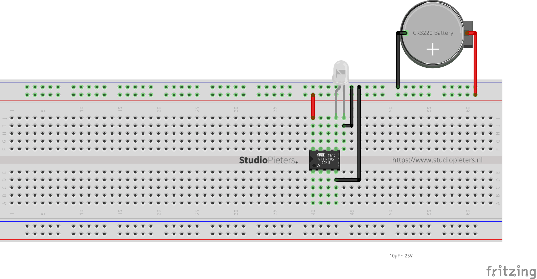
There it is the blink program running on a ATtiny13A with just a battery cell to power it. You can do many projects with low cost, low power and low space. Only your imagination is the limit here and the number of PWM pins of course.
DO YOU HAVE ANY QUESTIONS? LEAVE A COMMENT DOWN HERE.
REFERENCES
MCUdude. MicroCore is a lightweight Arduino hardware package for ATtiny13, ATtiny13A and ATtiny13V . (2020 )https://github.com/MCUdude/MicroCorey