
Electronics
Arduino nRF24L01 Wireless Remote with Two Nanos
Two Arduino Nanos with nRF24L01 radio modules as a wireless remote, tested with the RF24 library.
- Arduino
- 2 min read
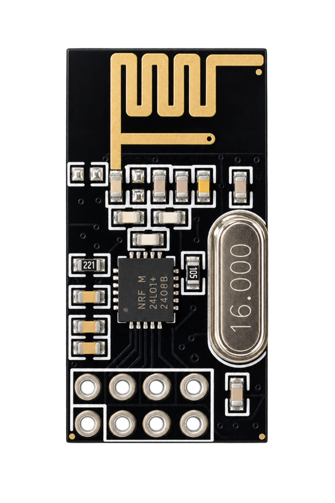
The nRF24L01+ is a small 2.4 GHz radio module that talks to an Arduino over SPI. This project connects two Arduino Nanos with one module each and uses them as a wireless remote: press a button on the transmitter and a led lights up on the receiver.
It is a test of the module with the RF24 library. The sketch is the led_remote example of that library, so the code itself is not repeated here.
The module
The module has eight pins. The supply pin is marked 3.3 V, so power it from the 3.3 V pin of the Nano and not from 5 V.
| Module pin | Function |
|---|---|
| GND | Ground |
| 3.3V | Supply |
| CE | Chip enable, from the Arduino |
| CSN | SPI chip select, from the Arduino |
| SCK | SPI clock |
| MOSI | SPI data from the Arduino |
| MISO | SPI data to the Arduino |
| IRQ | Interrupt, not used in this sketch |
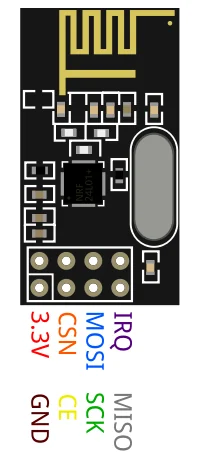
The diagram puts a capacitor on the supply of each module. See the Arduino Nano pinout for the pins of the board.
Wiring
The sketch sets up the radio on the SPI bus with pins 9 and 10 for CE and CSN. On a Nano the SPI pins are fixed: D13 is SCK, D12 is MISO and D11 is MOSI.
| Module pin | Arduino Nano pin |
|---|---|
| CE | D9 |
| CSN | D10 |
| SCK | D13 |
| MOSI | D11 |
| MISO | D12 |
| 3.3V | 3V3 |
| GND | GND |
How the sketch works
The same sketch runs on both boards. Pin A4 decides the role: leave it open and the board is the remote, connect it to GND and it is the led board.
| Setting | Value |
|---|---|
| Radio channel | 100 |
| Data rate | 250 kbps |
| Transmit power | The lowest level, RF24_PA_MIN |
| Buttons on the remote | Six, on pins 2 to 7 |
| Leds on the led board | Six, on pins 2 to 7 |
| Serial monitor | 115200 baud |
The remote reads its six buttons and sends their state when one of them changes. The led board receives the six states and switches a led when the matching button is pressed. Both boards print what they do to the serial monitor. The diagram shows the smallest version of this, with one button and one led.
Good to know
- The RF24 library is installed from the Library Manager of the Arduino IDE.
- The repository holds the sketch and two images and is under the MIT licence.
The project is in the Arduino—nRF24L01-Interfacing repository on GitHub.
Related
 Electronics
Raspberry Pi Zero W HAT Template for KiCad
A ready-made KiCad starting point for a Raspberry Pi Zero W HAT: the exact board outline, mounting holes and 40-pin header, plus a 3D model, MIT licensed. Includes a walkthrough for creating your own KiCad symbol.
Read more
Electronics
Raspberry Pi Zero W HAT Template for KiCad
A ready-made KiCad starting point for a Raspberry Pi Zero W HAT: the exact board outline, mounting holes and 40-pin header, plus a 3D model, MIT licensed. Includes a walkthrough for creating your own KiCad symbol.
Read more
 3D printing
OctoPrint Enclosure for a Raspberry Pi 4B
A 3D printable enclosure for a Raspberry Pi 4B running OctoPrint, with a relay module, vents and a USB camera, printed in PLA on an Ender 3 V2.
Read more
3D printing
OctoPrint Enclosure for a Raspberry Pi 4B
A 3D printable enclosure for a Raspberry Pi 4B running OctoPrint, with a relay module, vents and a USB camera, printed in PLA on an Ender 3 V2.
Read more
 Electronics
Blinds over MQTT with a NodeMCU and a Stepper Motor
A NodeMCU that moves blinds with a 28BYJ-48 stepper motor, set as a percentage over MQTT and used from Homebridge.
Read more
Electronics
Blinds over MQTT with a NodeMCU and a Stepper Motor
A NodeMCU that moves blinds with a 28BYJ-48 stepper motor, set as a percentage over MQTT and used from Homebridge.
Read more
More projects
Keep building.
Electronics, 3D printing and CNC builds, documented from the first idea to the last screw.
All projects