
Reference
ESP32-WROOM-32D Pinout
The pin reference for the ESP32-WROOM-32D module: 38 pads, 32 GPIOs of which 6 are tied to the flash, how to flash it and which pins are safe to use.
- 32 GPIOs
- 26 free
- 4 MB flash
- Wi-Fi 4 and Bluetooth 4.2 LE
Overview
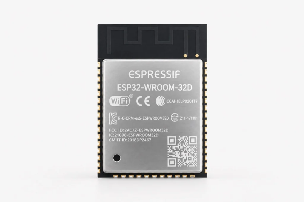
The ESP32-WROOM-32D is a small shielded module from Espressif with an ESP32 chip, a crystal, flash memory and a PCB antenna on one board of 18 by 25.5 mm. It has Wi-Fi and Bluetooth built in and runs your own firmware. Many ESP32 development boards, like the DevKitC and DevKit V1, are built around a module like this one.
Espressif marks the ESP32-WROOM-32D as not recommended for new designs (NRND) on its datasheet. It is still sold and still on many boards. For a new design use the ESP32-WROOM-32E, which has the same size and the same pad positions.
Wi-Fi 4 (802.11 b/g/n, 2.4 GHz) and Bluetooth v4.2 BR/EDR with BLE. Matter works over Wi-Fi. There is no 802.15.4 radio, so no Thread or Zigbee: that needs an ESP32-C6 or ESP32-H2.
Module and board
This guide covers the bare module. The pin names are the names of the module pads, as printed on the datasheet. A development board routes the same pads to its own headers, and the labels on the board can differ, so check them on your own board.
The drawings in this guide show the module from the top, with the antenna at the top, and from the back. The pads are numbered 1 to 38, going counter-clockwise from the top left. Pin 39 is the large exposed ground pad on the back.
Getting started
Most people use this module on a development board and not as a bare module, and these three steps assume a board with a USB connector. A bare module has no USB, see “Flashing the bare module” below for that.
Hello World: blink an LED
GPIO2 toggles once a second. The module itself has no LED, so wire an LED with a resistor of about 330 Ω between GPIO2 and ground. Some development boards, like the DevKit V1 type, already have an LED on GPIO2. Many others only have a power LED, so check your own board.
ESP-IDF
#include "freertos/FreeRTOS.h"
#include "freertos/task.h"
#include "driver/gpio.h"

#define LED_PIN GPIO_NUM_2

void app_main(void)
{
    gpio_reset_pin(LED_PIN);
    gpio_set_direction(LED_PIN, GPIO_MODE_OUTPUT);
    while (1) {
        gpio_set_level(LED_PIN, 1);
        vTaskDelay(pdMS_TO_TICKS(1000));
        gpio_set_level(LED_PIN, 0);
        vTaskDelay(pdMS_TO_TICKS(1000));
    }
}
Arduino IDE
#define LED_PIN 2   // GPIO2, wire an LED with a resistor to it

void setup() {
  pinMode(LED_PIN, OUTPUT);
}

void loop() {
  digitalWrite(LED_PIN, HIGH);
  delay(1000);
  digitalWrite(LED_PIN, LOW);
  delay(1000);
}
Build and flash with ESP-IDF using idf.py build flash monitor. These sketches are minimal examples and were not run on a board for this guide.
Specifications
Compute
| Chip | ESP32-D0WD |
| CPU | Dual-core Xtensa LX6, up to 240 MHz |
| Memory | 448 KB ROM, 520 KB SRAM |
| Flash | 4 MB, quad SPI |
| PSRAM | None |
Radio
| Wi-Fi | 802.11 b/g/n, 2.4 GHz, up to 150 Mbps |
| Bluetooth | v4.2 BR/EDR and Bluetooth LE |
| Antenna | On-board PCB antenna. The ESP32-WROOM-32U has a connector for an external antenna |
| Wi-Fi transmit current | See the datasheet for the current in each mode |
Physical and electrical
| Supply | 3.0 to 3.6 V, 3.3 V typical, the supply must deliver at least 0.5 A |
| Temperature | -40 to 85 °C |
| Size | 18.0 x 25.5 x 3.1 mm |
| Pads | 38, 1.27 mm pitch, and an exposed ground pad |
| GPIOs | 32, of which 6 (GPIO6 to GPIO11) are wired to the flash |
Keep an LED or other load on a GPIO to about 10 mA, and use a transistor or a driver chip for more.
Source: Espressif ESP32-WROOM-32D and ESP32-WROOM-32U datasheet, version 2.8.
Dimensions
The module is 18.0 by 25.5 mm and 3.1 mm thick, with a tolerance of 0.15 mm. The antenna area at the top is 6.19 mm long and thinner, 0.8 mm. There are 14 pads on each side and 10 along the bottom, all at 1.27 mm pitch, and the exposed ground pad on the back is 3.6 mm square. Keep copper and metal away from the antenna area on your own board.

Source: the Physical Dimensions section of the Espressif datasheet. The drawing is schematic.
Pinout diagram: top
The pads are numbered 1 to 38. Pads 1 to 14 are on the left, 15 to 24 along the bottom and 25 to 38 on the right, going up. The number in each label is the pad number, the name is the name on the datasheet and the second line gives the GPIO and what it can do.

The pads 17 to 22 carry the flash pins SD2, SD3, CMD, CLK, SD0 and SD1. They are connected to the flash on the module and are not meant for your own use.
Pinout diagram: back
The back is mirrored, so the pins swap sides. The large pad in the middle is pin 39, the exposed ground pad. Soldering it to ground is optional, but it helps to get heat out of the module. Use the right amount of solder paste, because too much lifts the module off the board.

Pins at a glance
The pins grouped by job. Only a few of them are special, the rest are normal I/O pins.

GPIO reference
Every GPIO that is available on the module, with its pad number and what it can do. ADC2 cannot be used while Wi-Fi is on, so read analog values on ADC1 (GPIO32 to GPIO39) when you use Wi-Fi.
| GPIO | Pin | Other functions | ADC | DAC | Touch | RTC | Notes |
|---|---|---|---|---|---|---|---|
| GPIO0 | 25 | CLK_OUT1, EMAC_TX_CLK | ADC2_CH1 | – | T1 | RTC11 | Strapping: low at reset = download mode |
| GPIO1 | 35 | TXD0 (U0TXD), CLK_OUT3 | – | – | – | – | UART0 TX, prints the boot log |
| GPIO2 | 24 | HSPIWP, HS2_DATA0, SD_DATA0 | ADC2_CH2 | – | T2 | RTC12 | Strapping: keep low or open at reset |
| GPIO3 | 34 | RXD0 (U0RXD), CLK_OUT2 | – | – | – | – | UART0 RX |
| GPIO4 | 26 | HSPIHD, HS2_DATA1, SD_DATA1 | ADC2_CH0 | – | T0 | RTC10 | |
| GPIO5 | 29 | VSPICS0, HS1_DATA6 | – | – | – | – | Strapping: SDIO timing, default high |
| GPIO6 | 20 | CLK, SPICLK | – | – | – | – | Wired to the on-module flash. Do not use |
| GPIO7 | 21 | SD0, SPIQ | – | – | – | – | Wired to the on-module flash. Do not use |
| GPIO8 | 22 | SD1, SPID | – | – | – | – | Wired to the on-module flash. Do not use |
| GPIO9 | 17 | SD2, SPIHD | – | – | – | – | Wired to the on-module flash. Do not use |
| GPIO10 | 18 | SD3, SPIWP | – | – | – | – | Wired to the on-module flash. Do not use |
| GPIO11 | 19 | CMD, SPICS0 | – | – | – | – | Wired to the on-module flash. Do not use |
| GPIO12 | 14 | MTDI, HSPIQ, HS2_DATA2, SD_DATA2 | ADC2_CH5 | – | T5 | RTC15 | Strapping: must be low at reset on this module |
| GPIO13 | 16 | MTCK, HSPID, HS2_DATA3, SD_DATA3 | ADC2_CH4 | – | T4 | RTC14 | JTAG TCK |
| GPIO14 | 13 | MTMS, HSPICLK, HS2_CLK, SD_CLK | ADC2_CH6 | – | T6 | RTC16 | JTAG TMS |
| GPIO15 | 23 | MTDO, HSPICS0, HS2_CMD, SD_CMD | ADC2_CH3 | – | T3 | RTC13 | Strapping: low at reset silences the boot log |
| GPIO16 | 27 | U2RXD, HS1_DATA4 | – | – | – | – | UART2 RX |
| GPIO17 | 28 | U2TXD, HS1_DATA5 | – | – | – | – | UART2 TX |
| GPIO18 | 30 | VSPICLK, HS1_DATA7 | – | – | – | – | VSPI SCK |
| GPIO19 | 31 | VSPIQ, U0CTS | – | – | – | – | VSPI MISO |
| GPIO21 | 33 | VSPIHD, EMAC_TX_EN | – | – | – | – | I2C SDA in the Arduino core |
| GPIO22 | 36 | VSPIWP, U0RTS | – | – | – | – | I2C SCL in the Arduino core |
| GPIO23 | 37 | VSPID, HS1_STROBE | – | – | – | – | VSPI MOSI |
| GPIO25 | 10 | EMAC_RXD0 | ADC2_CH8 | DAC1 | – | RTC6 | |
| GPIO26 | 11 | EMAC_RXD1 | ADC2_CH9 | DAC2 | – | RTC7 | |
| GPIO27 | 12 | EMAC_RX_DV | ADC2_CH7 | – | T7 | RTC17 | |
| GPIO32 | 8 | XTAL_32K_P | ADC1_CH4 | – | T9 | RTC9 | |
| GPIO33 | 9 | XTAL_32K_N | ADC1_CH5 | – | T8 | RTC8 | |
| GPIO34 | 6 | – | ADC1_CH6 | – | – | RTC4 | Input only, no pull-up or pull-down |
| GPIO35 | 7 | – | ADC1_CH7 | – | – | RTC5 | Input only, no pull-up or pull-down |
| GPIO36 | 4 | SENSOR_VP | ADC1_CH0 | – | – | RTC0 | Input only, no pull-up or pull-down |
| GPIO39 | 5 | SENSOR_VN | ADC1_CH3 | – | – | RTC3 | Input only, no pull-up or pull-down |
Almost any peripheral can be moved to other pins with the GPIO matrix, so the default pins above are a convention and not a limit.
Source: Espressif ESP32-WROOM-32D and ESP32-WROOM-32U datasheet, version 2.8.
Boot pins
Five pins are read at reset to decide how the chip boots. They are free to use as normal pins after boot, but what is connected to them while the chip starts matters.
| GPIO | Default | What it does at reset |
|---|---|---|
| GPIO0 | Pull-up | Low at reset starts the serial bootloader (download mode). High runs the program from flash |
| GPIO2 | Pull-down | Together with GPIO0 it selects the boot mode. Keep it low or open when you flash |
| GPIO12 (MTDI) | Pull-down | Selects the flash voltage. High at reset gives 1.8 V and a module with 3.3 V flash does not start, so keep it low at power-up |
| GPIO15 (MTDO) | Pull-up | Low at reset silences the boot messages on UART0 |
| GPIO5 | Pull-up | Sets the SDIO slave timing, leave it at its default |
A button, a relay or a sensor with a pull-up or pull-down on one of these pins can stop the module from starting. Choose other pins first.
Source: Espressif ESP32-WROOM-32D and ESP32-WROOM-32U datasheet, version 2.8.
Flashing the bare module
A development board does this for you. For a bare module you need a USB-to-serial adapter that works at 3.3 V and a stable 3.3 V supply that can deliver at least 0.5 A, because Wi-Fi sends in short, strong pulses.
| Module pin | Connect to | Note |
|---|---|---|
| 3V3 (pad 2) | 3.3 V supply | Not 5 V, that can damage the module |
| GND (pad 1, 15 or 38) | Ground of the supply and of the adapter | All grounds together |
| EN (pad 3) | 3.3 V through a resistor, and a reset button to ground | Never leave it floating |
| TXD0 (pad 35) | RX of the adapter | GPIO1, UART0 TX |
| RXD0 (pad 34) | TX of the adapter | GPIO3, UART0 RX |
| IO0 (pad 25) | Ground while the chip resets | Starts download mode, then release it |
| IO2 (pad 24) | Open or low | Leave it unconnected |
To flash: hold IO0 low, reset the module with EN, release IO0 and start the upload. Boards with an auto-reset circuit do this with the DTR and RTS lines of the adapter.
Source: Espressif ESP32-WROOM-32D and ESP32-WROOM-32U datasheet, version 2.8.
ESP32-WROOM-32D or ESP32-WROOM-32E
The two modules fit the same footprint, so one can replace the other on a board. The difference is in the chip revision, the flash options and the six pads in the middle of the bottom edge.
| ESP32-WROOM-32D | ESP32-WROOM-32E | |
|---|---|---|
| Chip | ESP32-D0WD | ESP32-D0WD-V3, or ESP32-D0WDR2-V3 with 2 MB PSRAM |
| GPIOs | 32, of which 6 are wired to the flash | 26 |
| Flash | 4 MB | 4, 8 or 16 MB |
| Pads 17 to 22 | Flash pins SD2, SD3, CMD, CLK, SD0, SD1 | Not connected |
| Temperature | -40 to 85 °C | -40 to 85 °C, or -40 to 105 °C (H4, H8) |
| Size and pad positions | 18.0 x 25.5 x 3.1 mm | The same |
| Status | Not recommended for new designs | Current |
See the ESP32-WROOM-32E guide for the newer module. For the other ESP32 chips, see the ESP32 family explained.
Real gotchas
- ADC2 stops working when Wi-Fi is on. Use an ADC1 pin (GPIO32 to GPIO39) for analog readings in a Wi-Fi project.
- GPIO34, 35, 36 and 39 are input only. They have no output driver and no internal pull-up or pull-down, so add an external resistor when you need one.
- GPIO12 high at power-up stops the module from starting. The module has 3.3 V flash, and a high level on this pin selects 1.8 V. Do not pull it up.
- EN must never float. Pull it high, and add a reset button to ground. A floating EN gives random resets.
- The module is 3.3 V only. A 5 V signal on a pin can damage it, use a level shifter.
- Wi-Fi sends in strong pulses. The supply must deliver at least 0.5 A, and a weak USB port or a long thin wire gives brown-out resets when the radio sends. Put a capacitor of 10 µF or more close to the 3V3 pin.
- GPIO6 to GPIO11 are wired to the flash. The module does not start if you use them for something else.
- Not recommended for new designs. If you design a board, use the ESP32-WROOM-32E, it has the same footprint.
- Keep the antenna area free. Copper, a metal case or a battery close to the PCB antenna reduce the range.
What to build
This module is the heart of many of the projects on this site, for example a HomeKit accessory with ESP-IDF, an ESP32 Matter device, a smart plug, or an LED controller for HomeKit. To update the firmware over the air, see the lifecycle manager. The ESP-WROOM-32 programmer is a board to flash the bare module.
Safety notes
Before you wire anything up
- Use 3.0 to 3.6 V on 3V3. 5 V on the supply pin or on a GPIO can destroy the module.
- Do not draw more than about 10 mA from a GPIO. The datasheet limits are higher but are tested at the edge of the output voltage.
- Check GPIO0, 2, 5, 12 and 15 before you use them as outputs, they are read at boot.
- GPIO34 to GPIO39 are input only.
- Never connect mains voltage to the module. If your project switches mains power, use a certified relay or power supply and read the safety notes of that part.
Conclusion
The ESP32-WROOM-32D is a small module with Wi-Fi, Bluetooth, a dual-core chip and 26 usable GPIOs, plus six pins that belong to the flash. It is still on many boards, but for a new design the ESP32-WROOM-32E has the same footprint. Keep an eye on the boot pins, keep ADC2 off when Wi-Fi is on, feed it a stable 3.3 V and keep the antenna area free.
All pin data and dimensions are from the Espressif datasheet of the module, checked on 6 November 2026. The pin labels in the drawings follow the pad numbers of that datasheet.
Related
 Reference
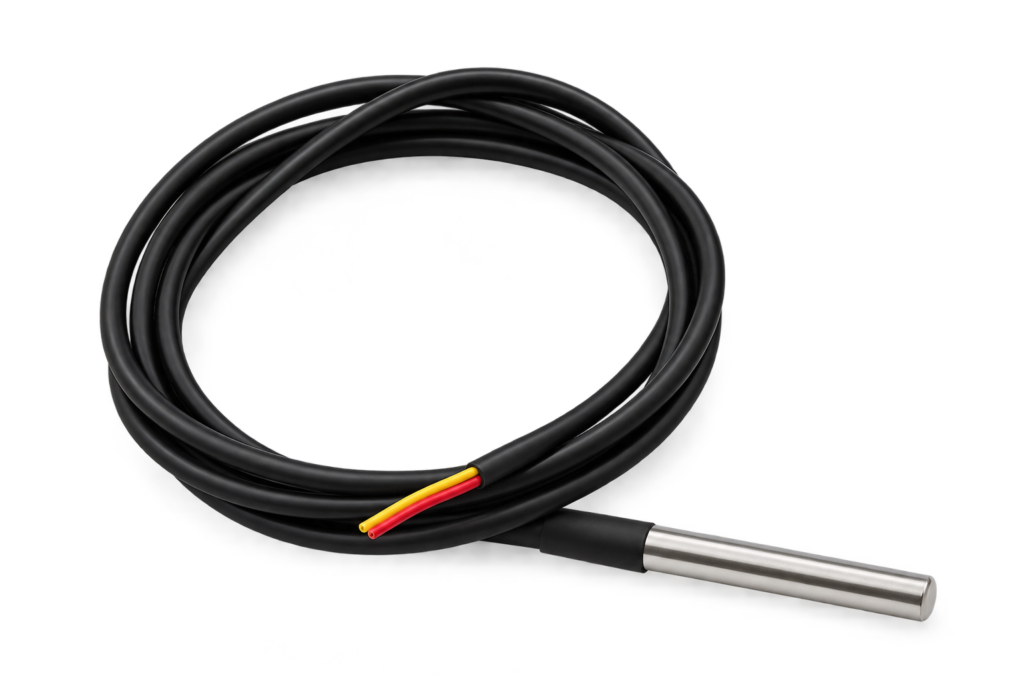
DS18B20 1-Wire Temperature Sensor
A rugged, waterproof-capable temperature sensor that can put dozens of measurement points on a single ESP32 GPIO. Covers how the 1-Wire bus and 64-bit ROM addressing work, the mandatory pull-up resistor, and parasite power mode.
Read more
 Reference
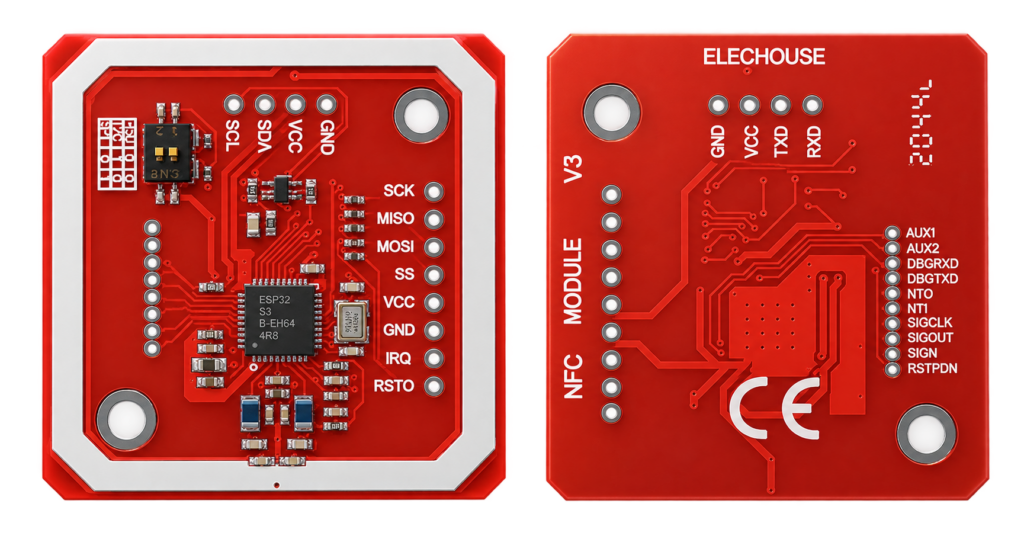
PN532 NFC Module Complete Guide
The PN532 reads and writes NFC tags, including the kind your phone already uses for tap-to-pay and tap-to-share, not just the 13.56MHz RFID cards the already-published RC522 handles. This guide covers its three interfaces, wiring it to an ESP32 over I2C, and when you actually need NFC over plain RFID.
Read more
 Reference
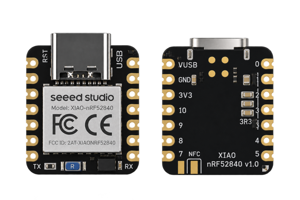
Seeed Studio XIAO nRF52840 Pinout
The Seeed XIAO nRF52840 pin reference: every pin with its nRF pin, the RGB and charge LEDs, the Sense sensors, battery reading and the double-tap bootloader.
Read more
More guides
Keep building.
From ESP32 HomeKit accessories to Arduino and ATtiny reference guides, there’s more where this came from.
All guides