
Reference
LILYGO T-Display-S3 Pinout
The real pin reference for LILYGO's T-Display-S3: an ESP32-S3 board with a built-in 1.9-inch color LCD, two buttons, and battery-monitoring support.
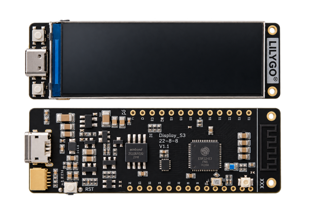
The T-Display-S3 is LILYGO’s ESP32-S3 board with a built-in 1.9-inch, 170×320 ST7789 color LCD wired straight to the board, no separate display module or wiring needed. Pin data below is sourced from LILYGO’s own GitHub repository for this board.
System-on-chip and board
Built on an ESP32-S3R8 (the PSRAM-equipped S3 variant): 16MB flash, 8MB octal PSRAM, plenty of headroom for a color UI. The onboard display uses an 8-bit parallel interface (not SPI), which is why it needs so many dedicated GPIOs, those pins aren’t available for your own use.
Built-in display pins
| Function | GPIO |
|---|---|
| Backlight | 38 |
| Chip select (CS) | 6 |
| Data/command (DC) | 7 |
| Write (WR) | 8 |
| Read (RD) | 9 |
| Reset | 5 |
| Data bus D0–D7 | 39–48 |
| Peripheral power enable | 15 |
GPIO15 must be set HIGH in your code before the display (and other onboard peripherals) will work at all. This is the single most common “blank screen” mistake with this board.
Buttons, battery, and other interfaces
| Function | GPIO / pin | Notes |
|---|---|---|
| Button 1 (BOOT) | GPIO0 | Also the flashing boot-mode button |
| Button 2 | GPIO14 | General-purpose, no fixed function by default |
| Battery voltage (ADC) | GPIO4 | Only reads correctly while USB-C is unplugged |
| I²C SCL | GPIO17 | |
| I²C SDA | GPIO18 | |
| Touch interrupt | GPIO16 | Header-exposed, not used by the onboard display itself |
| Touch reset | GPIO21 | |
| VBUS header pin | — | 5V, present while USB-connected |
| VBAT header pin | — | 4.2V, from an attached LiPo battery |
| 3V3 header pin | — | Regulated output, 100mA maximum load |
An optional expansion shield adds a microSD slot on GPIO11 (CMD), GPIO12 (CLK) and GPIO13 (D0), only relevant if you’ve fitted that shield.
Conclusion
The built-in display makes this a genuinely different board from a bare breakout, most of its GPIOs are already spoken for by the screen, plan your project’s wiring around what’s actually left rather than assuming the ESP32-S3’s full pin count is available. For a board with the same chip and no display, more free GPIOs, see the AI-S3.
Related
 Guide
HC-05 Bluetooth Module Pinout
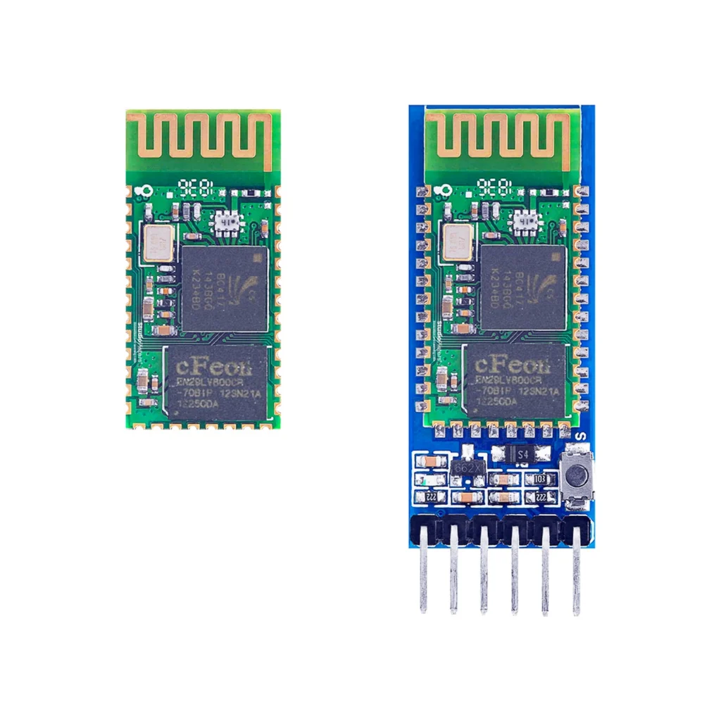
The complete pin reference for the HC-05: a UART-to-Bluetooth bridge available as a bare 34-pin module or a simple 6-pin breakout board.
Read more
Guide
HC-05 Bluetooth Module Pinout
The complete pin reference for the HC-05: a UART-to-Bluetooth bridge available as a bare 34-pin module or a simple 6-pin breakout board.
Read more
 Reference
SG90 Servo
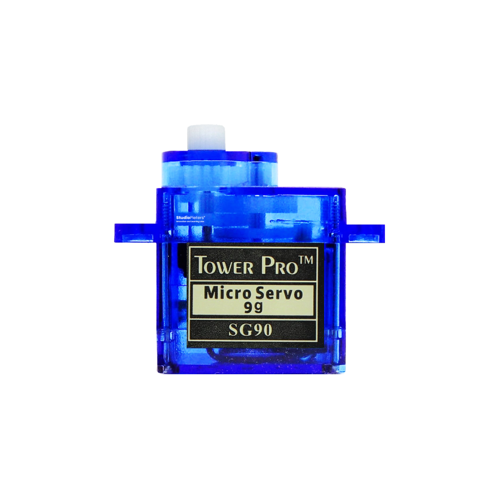
The classic 9-gram micro servo: a 3-wire PWM interface, ~180° of travel, and enough torque for pan-tilt mounts and small robotic arms. This guide covers the pinout, PWM pulse-width timing, wiring, and how it compares to the metal-gear MG90S.
Read more
Reference
SG90 Servo
The classic 9-gram micro servo: a 3-wire PWM interface, ~180° of travel, and enough torque for pan-tilt mounts and small robotic arms. This guide covers the pinout, PWM pulse-width timing, wiring, and how it compares to the metal-gear MG90S.
Read more
 Reference
SCD40 / SCD41 CO2 Sensor Complete Guide
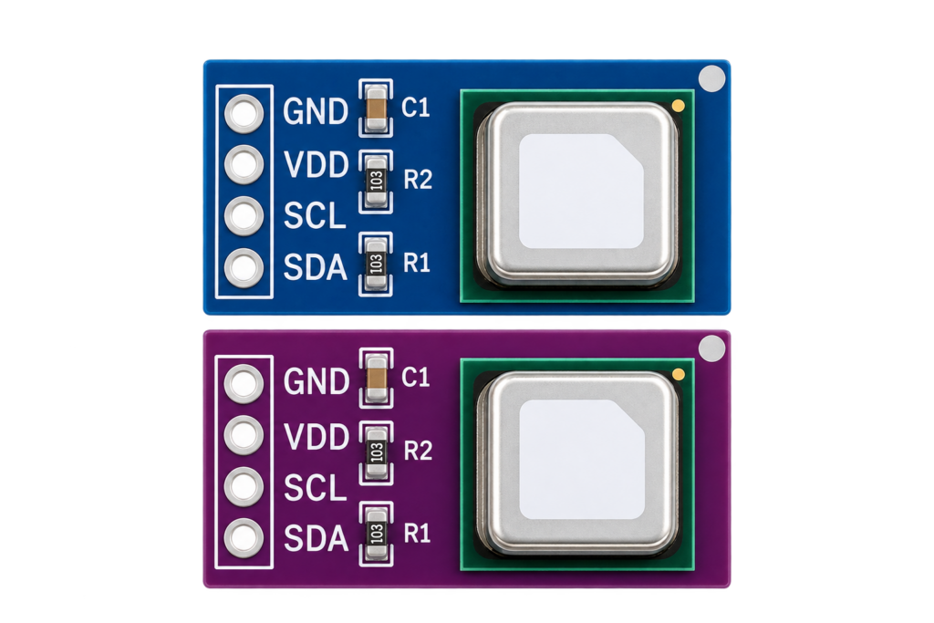
The SCD40 and SCD41 measure actual CO2 concentration using photoacoustic NDIR sensing, something a temperature/humidity sensor like the BME280 or SHT series cannot do at all. This guide covers both chips' real specs, wiring one to an ESP32, and the common beginner mix-up between CO2 sensing and air-quality/humidity sensing.
Read more
Reference
SCD40 / SCD41 CO2 Sensor Complete Guide
The SCD40 and SCD41 measure actual CO2 concentration using photoacoustic NDIR sensing, something a temperature/humidity sensor like the BME280 or SHT series cannot do at all. This guide covers both chips' real specs, wiring one to an ESP32, and the common beginner mix-up between CO2 sensing and air-quality/humidity sensing.
Read more
More guides
Keep building.
From ESP32 HomeKit accessories to Arduino and ATtiny reference guides, there’s more where this came from.
All guides