
Reference
INA219 / INA226 Voltage, Current and Power Sensor Complete Guide
The INA219 and INA226 measure voltage, current and power on a low-voltage DC bus over I2C, using a shunt resistor and Ohm's law, not the mains-AC energy-meter ICs this site already covers. This guide covers both chips' real specs, wiring one to an ESP32, and which to pick for a battery or power-budget project.
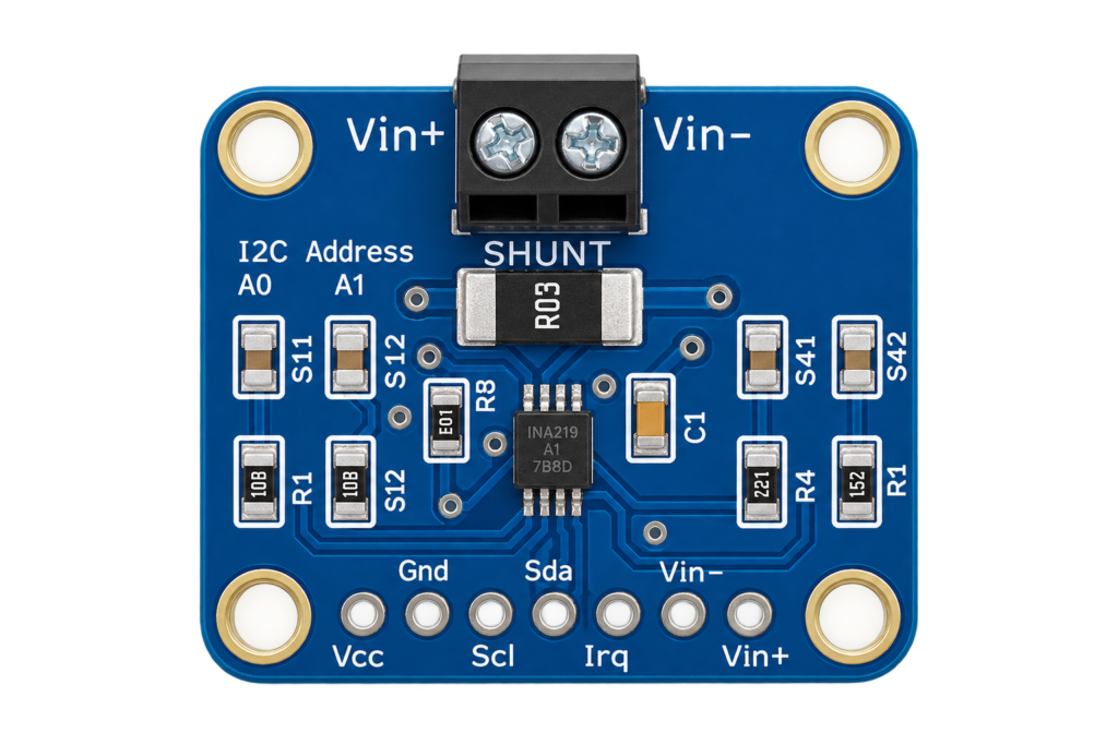
The INA219 and INA226 are Texas Instruments current/power monitor ICs: they measure the tiny voltage drop across a shunt resistor in series with a DC load, then report current, bus voltage and power over I2C. This is a different job from the already-published BL0937/BL0942 energy-meter ICs on this site, those measure mains AC power for a smart plug, these measure low-voltage DC bus power, for example how much current a battery pack, solar panel or 3.3V/5V rail is actually drawing.
INA219 vs. INA226: real differences
| INA219 | INA226 | |
|---|---|---|
| ADC resolution | 12-bit | 16-bit |
| Max current (with a 0.1Ω shunt, 3.2A range) | 3.2A (has a built-in PGA to boost sensitivity) | 0.8A (no PGA, use a smaller shunt for higher current) |
| Selectable I2C addresses | 4 (via 2 address pins) | 16 (via 2 address pins) |
| Default I2C address | 0x40 | 0x40 |
The INA219 handles higher current out of the box thanks to its programmable gain amplifier. The INA226 trades that for finer resolution and more selectable addresses, useful when monitoring several rails on one I2C bus. For most single-battery or single-rail hobby monitoring, either works, pick the INA219 if you’re already reaching for its very common Adafruit breakout, or the INA226 if you specifically need its extra resolution or address count.
Wiring to an ESP32
Both chips measure current by sitting in series with the load’s supply line, through the shunt resistor built into the breakout board.
| Pin | Function | ESP32 Pin |
|---|---|---|
| VCC | Logic power, 3V–5.5V | 3.3V |
| GND | Ground | GND |
| SDA | I2C data | GPIO21 |
| SCL | I2C clock | GPIO22 |
| VIN+ / VIN− | Shunt terminals, wired in series with the load being measured | — (power path, not logic) |
Arduino code (Adafruit INA219 library)
#include <Wire.h>
#include <Adafruit_INA219.h>

Adafruit_INA219 ina219;

void setup() {
  Serial.begin(115200);
  Wire.begin(21, 22);
  if (!ina219.begin()) {
    Serial.println("Failed to find INA219");
    while (1) delay(10);
  }
}

void loop() {
  float busVoltage = ina219.getBusVoltage_V();
  float current_mA = ina219.getCurrent_mA();
  float power_mW = ina219.getPower_mW();

  Serial.print("Bus Voltage: "); Serial.print(busVoltage); Serial.println(" V");
  Serial.print("Current: "); Serial.print(current_mA); Serial.println(" mA");
  Serial.print("Power: "); Serial.print(power_mW); Serial.println(" mW");

  delay(1000);
}
Install “Adafruit INA219” via the Arduino Library Manager. For the INA226, there’s no official Adafruit library, the community RobTillaart/INA226 library is a well-maintained alternative with a similar API.
Practical Applications
- Battery fuel gauging: track real current draw to estimate remaining runtime.
- Solar panel monitoring: measure actual power output under real conditions.
- Power-budget debugging: find which part of a project is drawing more current than expected.
- Overcurrent protection logic: cut power in software if current exceeds a safe threshold.
Conclusion
The INA219 and INA226 give you real voltage/current/power visibility into a DC bus over I2C, complementing (not duplicating) the mains-AC BL0937/BL0942 guides already on this site. Either pairs cleanly with an ESP32 over I2C.
Related
 Reference
ESP32-S3 Zero / Super Mini Pinout
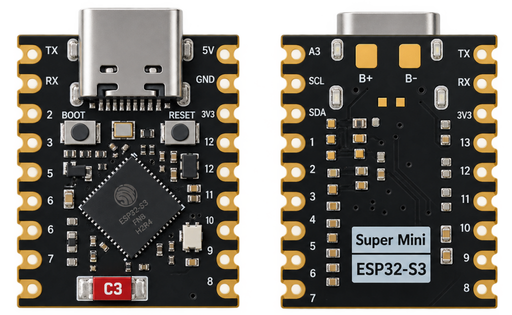
The real pin reference for the ESP32-S3-Zero-style board: a coin-sized ESP32-S3 devkit sold under names like "ESP32-S3 Zero" and "ESP32-S3 Super Mini" by Waveshare and several other sellers.
Read more
Reference
ESP32-S3 Zero / Super Mini Pinout
The real pin reference for the ESP32-S3-Zero-style board: a coin-sized ESP32-S3 devkit sold under names like "ESP32-S3 Zero" and "ESP32-S3 Super Mini" by Waveshare and several other sellers.
Read more
 Reference
MPU6050 Accelerometer + Gyroscope Complete Guide
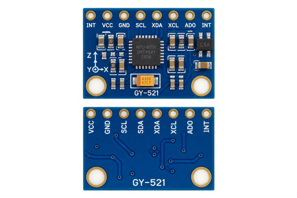
The MPU6050 packs a 3-axis accelerometer and 3-axis gyroscope on one die with an onboard motion-fusion processor, for around the price of a single sensor. This guide covers its real I2C addressing, pinout, and wiring one to an ESP32.
Read more
Reference
MPU6050 Accelerometer + Gyroscope Complete Guide
The MPU6050 packs a 3-axis accelerometer and 3-axis gyroscope on one die with an onboard motion-fusion processor, for around the price of a single sensor. This guide covers its real I2C addressing, pinout, and wiring one to an ESP32.
Read more
 Reference
Guide to the HWFS-1 Anemometer
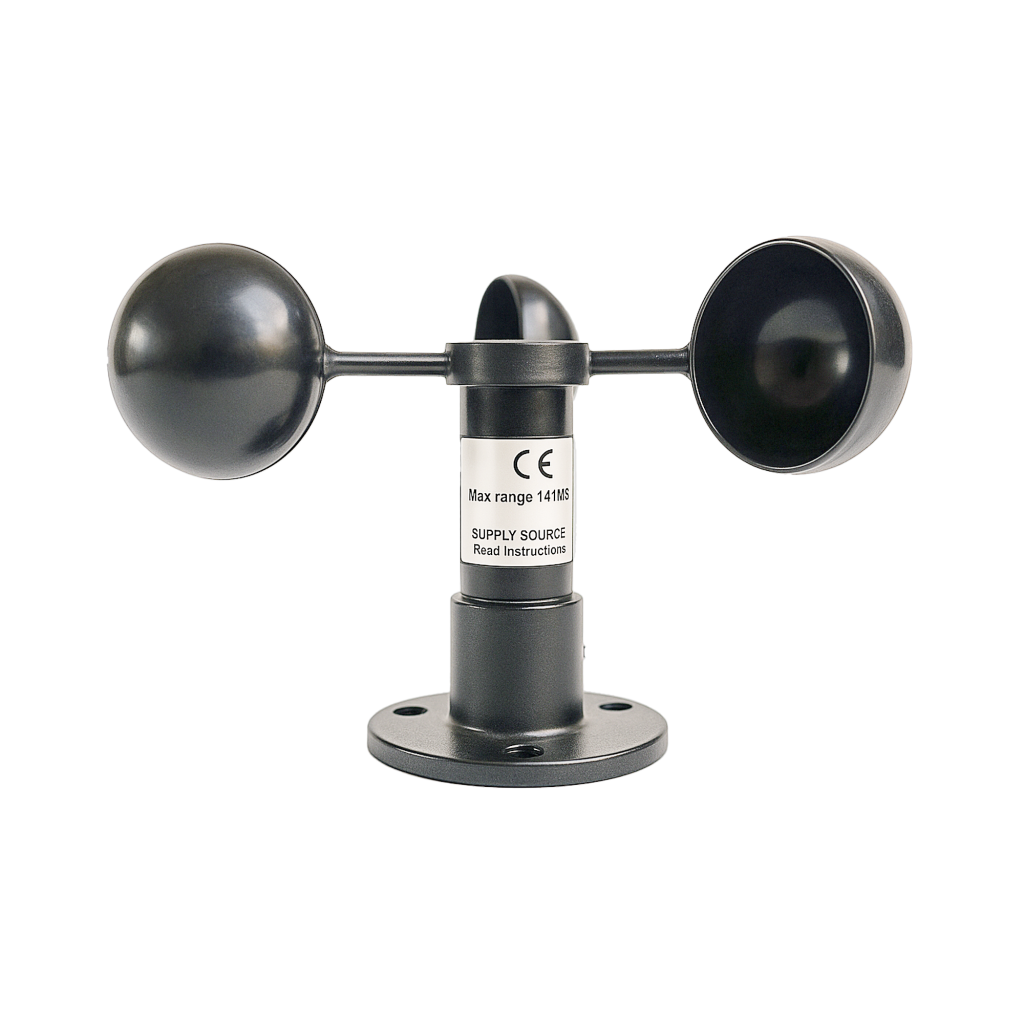
A passive, cup-style wind speed sensor with a built-in voltage generator, no external power needed. This guide covers the analog output, wiring to an ESP32 ADC pin, and the calibration formula to convert voltage into km/h or m/s.
Read more
Reference
Guide to the HWFS-1 Anemometer
A passive, cup-style wind speed sensor with a built-in voltage generator, no external power needed. This guide covers the analog output, wiring to an ESP32 ADC pin, and the calibration formula to convert voltage into km/h or m/s.
Read more
More guides
Keep building.
From ESP32 HomeKit accessories to Arduino and ATtiny reference guides, there’s more where this came from.
All guides