
Reference
Audio Amplifier for ESP32 and Arduino
How to make sound with a microcontroller: analog versus I2S amplifiers, the MAX98357A with an ESP32-S3, the PAM8403 and other analog modules, speakers, power and noise.
- ESP32
- Arduino
- 9 min read
A microcontroller pin can’t drive a speaker. It can send a signal, but not the current. To make sound you need an amplifier between the board and the speaker. For an ESP32 or an Arduino there are two kinds, and choosing the right one depends on the board you use.
In this guide we cover:
- Analog and I2S amplifiers, and which one fits your board
- The MAX98357A I2S amplifier with an ESP32-S3
- The PAM8403 and other analog amplifiers
- Speakers, power and noise
- How I use it in the Pit Droid backpack
Analog or I2S?
Almost every small amplifier module is a class D amplifier: efficient and small, so it doesn’t get hot. The difference is how the audio gets in:
| Analog amplifier | I2S amplifier | |
|---|---|---|
| Example | PAM8403 (stereo), PAM8302 (mono) | MAX98357A |
| Input | An analog audio signal | A digital I2S signal, with 3 pins |
| Needs | A DAC, or a PWM signal with a filter | An I2S output on your board |
| ESP32 (the first one) | Has two DACs, which can drive it | Works |
| ESP32-S3 | No DAC, so it needs more parts | Works. The easy choice |
| Arduino Uno | No DAC, PWM audio is poor | No I2S |
| Sound quality | Depends on the signal source | Clean, digital to the amplifier |
If you use an ESP32-S3, take an I2S amplifier. The S3 has no DAC, so an analog amplifier would need an extra DAC or a filtered PWM signal.
The MAX98357A I2S Amplifier
The MAX98357A is a mono I2S class D amplifier from Analog Devices (Maxim) that turns the digital audio from your board straight into speaker power. It is the usual choice for ESP32 audio projects.
| Parameter | Value |
|---|---|
| Supply voltage | 2.5 V to 5.5 V |
| Output power | About 3 W into 4 Ω at 5 V and 1.3 W at 3.3 V (10 percent distortion) |
| Speaker | 4 to 8 Ω (4 Ω or more), connected directly to the amplifier (the output is bridged) |
| Input | I2S, 3.3 V or 5 V logic |
| Pins | VIN, GND, DIN, BCLK, LRC, GAIN, SD |
Pin functions:
| Pin | Function |
|---|---|
| VIN | Power. Use 5 V for the most output |
| GND | Ground |
| DIN | The audio data from your board |
| BCLK | Bit clock |
| LRC | Left/right (word select) clock |
| GAIN | Sets the gain, 9 dB if left open |
| SD | Shutdown and channel select, see below. On the Adafruit board a resistor sets it to a left and right mix |
Gain
| GAIN pin | Gain |
|---|---|
| 100 kΩ to GND | 15 dB |
| Directly to GND | 12 dB |
| Left open (default) | 9 dB |
| Directly to VIN | 6 dB |
| 100 kΩ to VIN | 3 dB |
The gain is read at power up, so switch the power off and on after you change it.
Disclosure: links marked * are affiliate links. If you buy through them I may earn a small commission at no extra cost to you. It doesn’t change what I recommend.
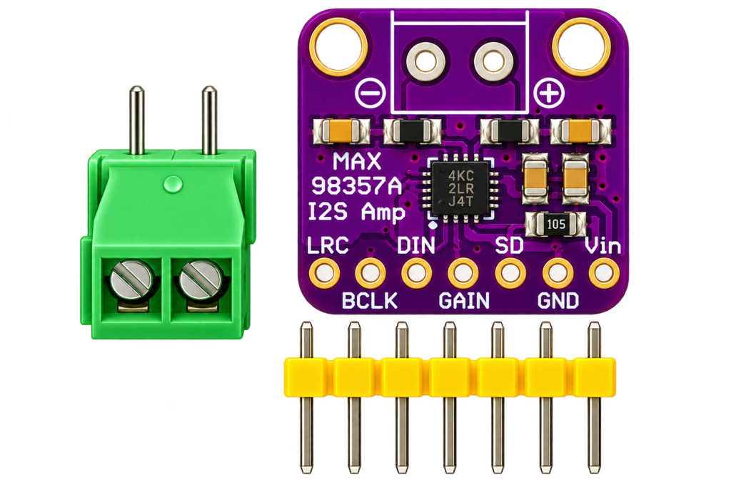
The amplifier module I use in the backpack: amplifier*. Check which chip is on your board: the small black square is printed with its name. The pins and the numbers above are for the MAX98357A.
Module pinout diagram
The breakout has seven pins in one row and a screw terminal for the speaker. This is the front of the board with the function of every pin, and the back with the pins mirrored.

Back of the board
The back has the printed key data: 4 to 8 ohm, 3 W, 2.5 V to 5.5 V, the default gain of 9 dB and the left and right mix on the SD pin.

The pin names are as printed on the board. The drawing follows the common breakout with the pin order LRC, BCLK, DIN, GAIN, SD, GND and Vin. Boards from other sellers can have a different order, so compare the silkscreen before you wire.
Dimensions
The breakout is about 17.8 x 19.05 mm. The seven pins are on a 2.54 mm pitch, 15.24 mm from the first to the last pin, and there are two mounting holes next to the screw terminal.

These sizes are read from the drawing of the board, using the 2.54 mm pin pitch as the scale, and not measured on a board. Boards from other sellers can differ.
The SD pin: shutdown and channel select
The SD pin does two jobs. The voltage on it switches the amplifier off or chooses what it plays, because the MAX98357A is a mono amplifier that receives a stereo I2S signal.
| Voltage on SD | What the amplifier does |
|---|---|
| Below 0.16 V | Shutdown, no sound |
| 0.16 V to 0.77 V | Plays the mix of left and right, (L + R) / 2 |
| 0.77 V to 1.4 V | Plays the right channel only |
| Above 1.4 V | Plays the left channel only |
The chip has an internal 100 kΩ resistor from SD to ground, so you set the voltage with a resistor to Vin. The Adafruit breakout has a 1 MΩ resistor from SD to Vin, which gives the mix of left and right at 5 V and at 3.3 V. To get only the left or the right channel, or to switch the amplifier off from a GPIO, you have to change that resistor or drive the pin yourself.
The source for the voltage ranges is the Adafruit guide for the MAX98357A.
Connecting It to an ESP32-S3
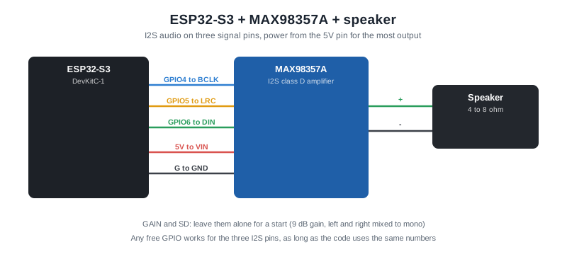
| MAX98357A | ESP32-S3-DevKitC-1 | Note |
|---|---|---|
| VIN | 5V | Or 3V3, but then there is less power |
| GND | G | Ground |
| DIN | GPIO6 | Data out |
| BCLK | GPIO4 | Bit clock |
| LRC | GPIO5 | Word select |
Any free GPIO works for the I2S pins, because the ESP32-S3 can route them through its pin matrix. The numbers must match the ones in your code. On the N8R8 and N16R8 boards, don’t use GPIO35, 36 or 37.
For the software, use the I2S driver of the ESP32 Arduino core (File > Examples > ESP_I2S) or the ESP-IDF i2s_std driver. Old code that uses driver/i2s.h may not work on the newer core, so look for an example that matches your version. A library such as ESP32-audioI2S plays WAV and MP3 files from an SD card or from flash.
Example: play a test tone
A short sketch for the ESP32-S3-DevKitC-1 with the wiring above. It plays a 440 Hz tone through the ESP_I2S library of the Arduino ESP32 core.
#include <ESP_I2S.h>

const int BCLK = 4;     // MAX98357A BCLK
const int LRC  = 5;     // MAX98357A LRC (word select)
const int DIN  = 6;     // MAX98357A DIN
const int SAMPLE_RATE = 16000;
const int TONE_HZ = 440;

I2SClass i2s;

void setup() {
  Serial.begin(115200);
  i2s.setPins(BCLK, LRC, DIN);   // bit clock, word select, data out
  if (!i2s.begin(I2S_MODE_STD, SAMPLE_RATE, I2S_DATA_BIT_WIDTH_16BIT, I2S_SLOT_MODE_STEREO)) {
    Serial.println("I2S failed to start");
    while (true) delay(1000);
  }
}

void loop() {
  const int samplesPerWave = SAMPLE_RATE / TONE_HZ;
  for (int i = 0; i < samplesPerWave; i++) {
    int16_t s = (int16_t)(sin(2.0 * PI * i / samplesPerWave) * 3000);   // low volume
    int16_t frame[2] = { s, s };                                         // left and right
    i2s.write((uint8_t *)frame, sizeof(frame));
  }
}
I did not run this sketch on a board, it follows the ESP_I2S API of the Arduino ESP32 core, and the function names can differ between core versions. If you hear nothing, check the SD pin, the wiring and that the pin numbers in the sketch match your wires. Keep the amplitude low first: 3000 of 32767 is a quiet tone.
Analog Amplifiers: PAM8403 and Friends
| Chip | Channels | Typical power | Supply | Remark |
|---|---|---|---|---|
| PAM8403 | Stereo | About 3 W per channel into 4 Ω at 5 V | 2.5 V to 5.5 V | Very cheap, needs an analog signal |
| PAM8302 | Mono | About 2.5 W into 4 Ω at 5 V | 2.0 V to 5.5 V | Small, mono |
| LM386 | Mono | Under 1 W | 4 V to 12 V | Old and noisy, but simple |
These work well with an ESP32 (the original has two DAC pins, GPIO25 and GPIO26) and with a Raspberry Pi audio jack. With a board without a DAC, such as an Arduino Uno or an ESP32-S3, you need a PWM signal with an RC filter, or an extra DAC chip. The sound is then poorer than with I2S.
Keep the signal wire short and shielded if you can, and power the amplifier from a clean supply. Many noise problems with these modules come from the power rails.
Speakers
- Impedance: match it to the amplifier, usually 4 to 8 Ω.
- Power rating: choose a speaker that handles at least what the amplifier can give, or keep the volume low in code.
- Size: a bigger speaker in an enclosure sounds better than a small bare one. For the Pit Droid backpack I picked a small one that fits: speaker*.
- Magnets: keep a speaker away from compasses and sensors that react to magnets.
Practical Engineering Tips
- Power matters. At full volume an amplifier draws several hundred milliamps, up to about an ampere. Don’t power it from a weak 3.3 V pin.
- One common ground for the amplifier, the board and the supply, so that you don’t get hum.
- Start quiet. Set the volume low in code and raise it. Distortion and heat show up at full volume.
- Don’t connect the output to ground or another amplifier on a bridged amplifier like the MAX98357A: both outputs carry the signal.
- Keep servo wires away from audio wires. Servo current spikes can come through as clicks.
Real gotchas
- No sound at all. The most common causes are a wrong pin number in the code, DIN and BCLK swapped, no common ground, and the SD pin being held low, which is the shutdown state.
- Only one channel. The amplifier is mono. The voltage on the SD pin decides whether you hear left, right or the mix.
- 4 Ω or more. The speaker impedance must be 4 Ω or higher. A lower value can overload the amplifier.
- Power supply. Adafruit recommends a supply of at least 800 mA. A weak USB port makes the sound crackle or resets the ESP32.
- Gain changes need a power cycle. The gain is read at power-up, so switching it with a wire while running does nothing until you restart.
- MCLK is not needed. The MAX98357A makes its own clock from BCLK, so you leave MCLK out.
- Both speaker terminals carry signal. The output is bridged: no terminal is ground. Do not connect either terminal to ground or to another amplifier.
- Check the chip on your board. Cheap boards sometimes carry another amplifier chip with a similar layout. The name is printed on the small black square.
In the Pit Droid
The animatronic Pit Droid has a backpack with room for a battery, a controller and a loudspeaker. Droid Division includes a folder with Pit Droid sounds, so the droid can play them through the amplifier. The parts are in the hardware list, and the controller is an ESP32-S3-DevKitC-1.
Conclusion
For an ESP32-S3, take an I2S amplifier like the MAX98357A and a 4 to 8 Ω speaker, and power it from 5 V. For the original ESP32 and boards with a DAC, a cheap PAM8403 also works. Whatever you choose, give it clean power and a common ground.
Related
 Reference
Everything You Need to Know About the LD33V
A fixed 3.3V linear regulator from the LD1117 family, the go-to way to power ESP modules, sensors and RF radios from a higher unregulated input. This guide covers dropout voltage, required capacitors, power dissipation, and how to avoid the overheating and brownout problems that come with powering an ESP32 from one.
Read more
 Reference
The Complete Guide to the HC-SR501 PIR Motion Sensor
One of the cheapest ways to add motion detection to a project: a passive infrared sensor with adjustable delay and sensitivity, a simple digital HIGH/LOW output, and both retriggerable and non-retriggerable modes.
Read more
Reference
HomeKit or Matter for Your ESP32? How to Choose
HomeKit and Matter both give you local control from an ESP32. Which one fits depends on where the device should work, which chip you have and whether you plan to sell it.
Read more
More guides
Keep building.
From ESP32 HomeKit accessories to Arduino and ATtiny reference guides, there’s more where this came from.
All guides