Have you ever wanted to create a project that involved non-contact detection, such as detecting the closing of a door, counting the number of revolutions of a wheel, or creating a speedometer? Then this blog about the Hall effect sensor is for you.
This project uses a Hall effect sensor to detect the presence of a magnet. Every time a magnet moves past this sensor, it can detect it. This sensor can be used for many different things. For example, if we need to detect a door closing; then we just need to attach a magnet to the door and a hallway sensor to the frame of the door. Whenever the door closes, the magnet is placed at the hall sensor and we can detect that the door is closed.

Likewise, the same principle can be used to make a speedometer for a bicycle or any other vehicle. If a magnet is attached to the wheel and a Hall sensor is placed somewhere in the frame of the bike, the time it takes for the wheel to complete one revolution can be measured, and with a little more math we can measure the movement of the bike detect speed!
How does it work.
The Hall sensor works on the Hall effect principle, which states that when a magnetic field is applied in a direction perpendicular to the flow of electric current in a conductor, a potential difference is induced. This voltage can be used to detect whether the sensor is near a magnet or not. The microcontroller can detect this voltage change through its interrupt pin and determine if the magnet is near the sensor or not. The basic operation of the Hall sensor is shown in the image below.
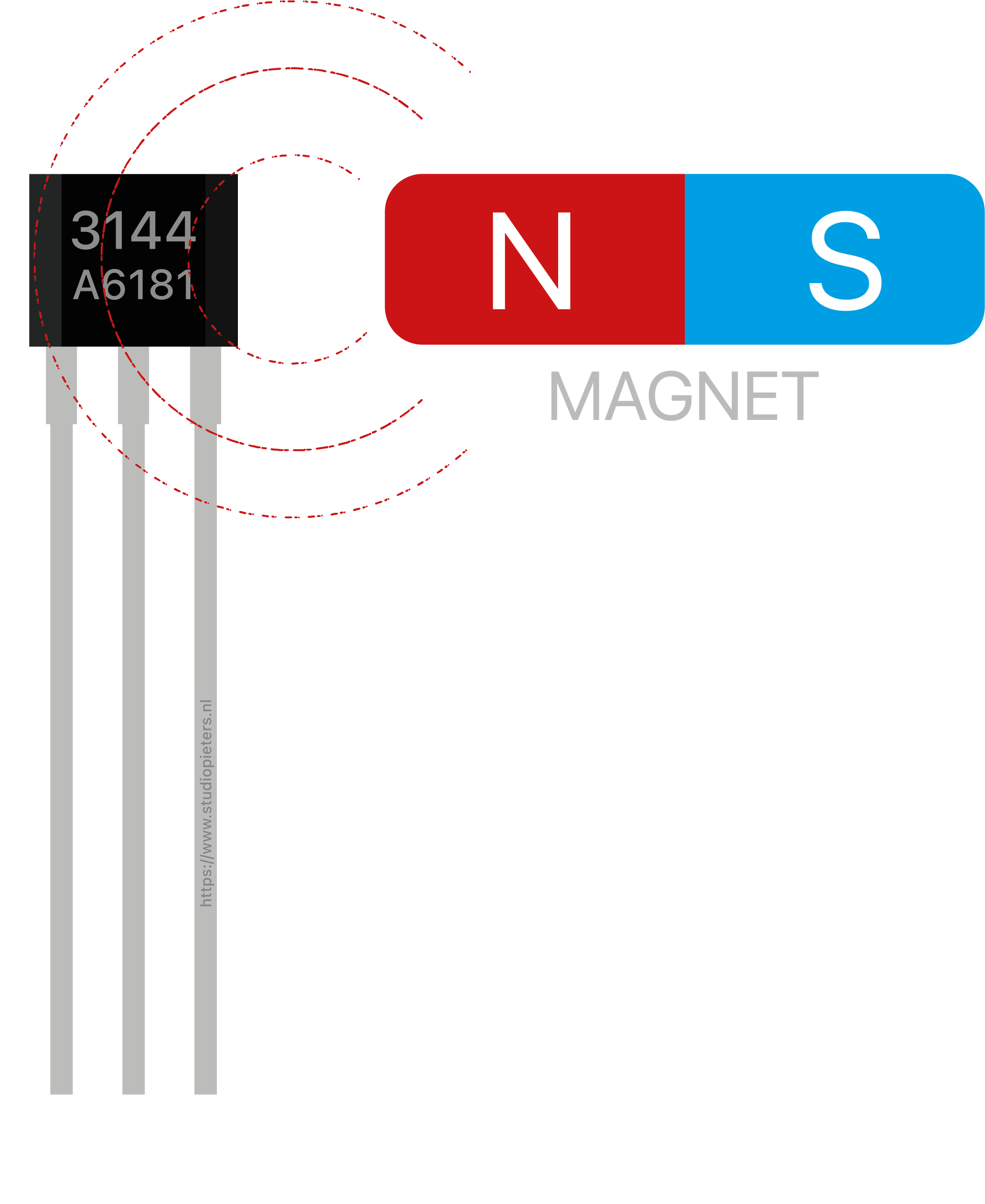
Note: I made a little mistake, the Hall sensor works ont he South Pole and not on the North Pole of the magnet.
There are many types of Hall sensors, and certain types are better for certain applications. For applications where detection speed is not critical, common Hall sensors such as A3144E can be used. For applications requiring high speed detection, such as in the case of speedometers, high frequency Hall sensors should be used. There are two main types of Hall effect sensors: latching and non-latching.
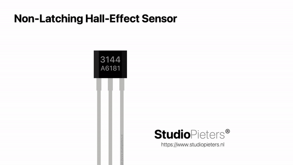
Non-Latching Hall-Effect Sensor
For example the AH1815 is an integrated Hall-Effect non-latched sensor. The sensor gives an output HIGH voltage whenever the north pole of a magnet is brought close to it, and switches LOW whenever the magnet is removed. I personally prefer non-latching Hall effect sensors like the 3144 for my projects.
Note: The same mistake here, the Hall sensor works ont he South Pole and not on the North Pole of the magnet.
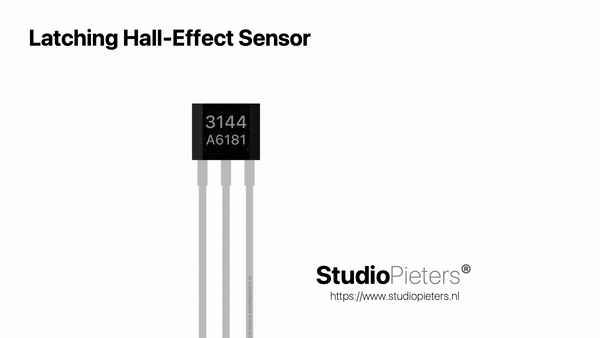
Latching Hall-Effect Sensor
For Example the US1881 is an integrated Hall-Effect latched sensor. The sensor gives out an output HIGH (5V) voltage whenever the north pole of a magnet is brought close to it. Even when the magnet is removed, the sensor still outputs a HIGH voltage and does not go LOW (0V) until the south pole of the magnet is brought close to it. These sensors that latch on to a particular state are called latched Hall effect sensors
Note: The same mistake here, the Hall sensor works ont he South Pole and not on the North Pole of the magnet, sorry about that.
The 3144
The 3144 is a high sensitivity digital unipolar Hall IC with single output. The 3144 Hall-effect sensor includes the following on a single silicon chip: reverse voltage protector, voltage regulator, temperature compensation circuit, Hall-voltage generator, signal amplifier, Schmitt trigger and open-collector output driver, etc. The integrated voltage regulator and temperature compensation circuit ensure that the sensor works stably in a wide voltage and temperature range. The reverse voltage protection circuit prevents the sensor from being damaged by reverse voltage.

The 3144, produced with bipolar technology, is more stable and reliable. It is available in three package types: SOT-23-3L (Type M), SOT-89 (Type S), and TO-92 (Type UA). Each package is lead (Pb) free, with 100% matte tin plated leadframes.
Hall-effect sensor Specifications:
- Digital Output Hall-effect sensor (non-latched)
- Operating voltage: 4.5V to 28V (typically 5V)
- Output Current: 25mA
- Can be used to detect both the poles of a magnet
- Output voltage is equal to operating voltage
- Operating temperature: -40°C to 85°C
- Turn on and Turn off time is 2µs each
- Inbuilt reverse polarity protection
Hall sensors have three pins: VCC (5V), GND and Dout (signal). The pinout of a Hall sensor is as shown below:
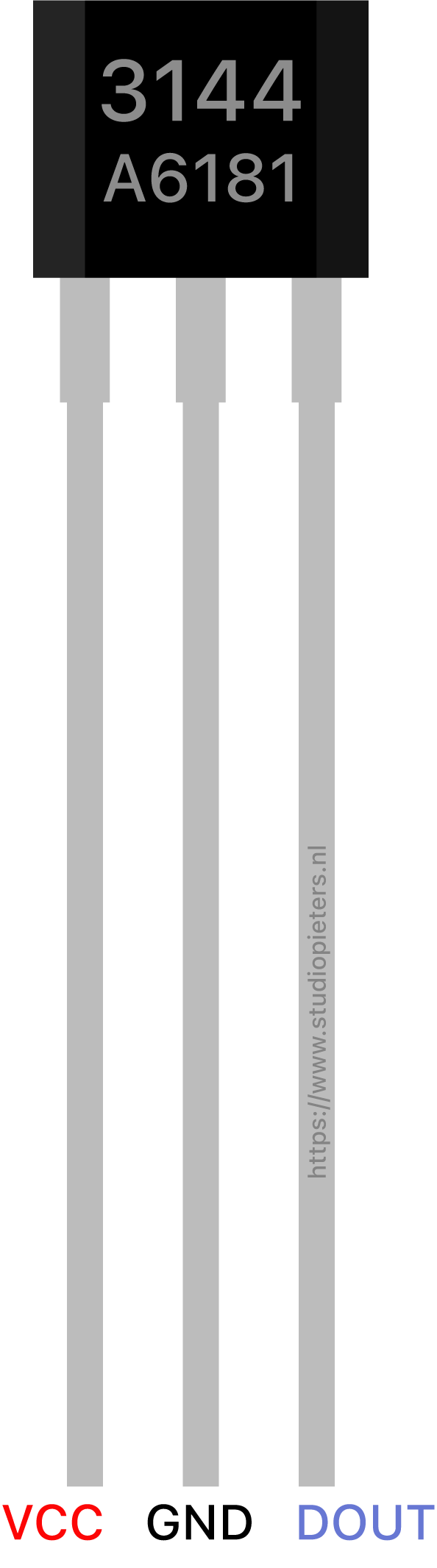
| No: | Pin Name | Description |
| 1 | +5V (Vcc) | Used to power the hall sensor, typically +5V is used |
| 2 | Ground | Connect to the ground of the circuit |
| 3 | Output | This pin goes high, if magnet detected. Output voltage is equal to Operating voltage. |
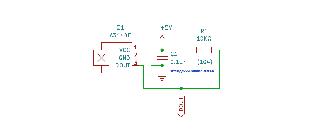
Circuit diagram
In the circuit diagram the resistor R1 (10KΩ) is used as a pull-up resistor and the capacitor C1 (0.1µF) is used to filter any noise that might be coupled with the digital output.
Scheme
Pairing the Hall sensor with Arduino Nano is very easy. The sensor’s VCC is connected to the Arduino Nano’s 5V power pin. The GND of the sensor is connected to the GND pin on the Arduino Nano. The Vout or signal pin of the Hall sensor is connected to the interrupt pin of the Arduino Nano D2 (digital pin 2). Furthermore, a 10KΩ resistor is connected between the VCC and Vout pins of the Hall sensor. This is done to pull the output of the Hall sensor to 5V. The connections are made as shown below:

The Code
After you are done connecting the Hall sensor to your Arduino Nano, you will need to upload the code to the board and test it. The Arduino Nano Hall sensor code can be used to detect a magnet and count the number of times it detects it. This is a very simple Arduino code that uses the Arduino Nano interrupt D2 (digital pin 2).
Whenever the Hall sensor detects a magnet, it outputs a HIGH (5V) voltage to its Vout pin. The interrupt pin of the Arduino Nano that is connected to Vout detects this rising (HIGH) voltage through the function: magnet_detect. The serial monitor prints “detect” when a magnet is brought close to the sensor.
Applications
To show the applications of this project, I installed the sensor on my door frame. I also attached a small magnet to my door. So when my door closes I can detect it. This can also be used as a burglar alarm system by connecting it to some lights and sirens.

You can also use this sensor to make a speedometer for your bike. A small magnet needs to be attached to your wheel and the Hall sensor can be attached to the frame of your bike. The number of rotations the wheel makes and the time it takes can be measured via the Hall sensor. And after doing some calculations on this data, you can display the speed of your bike in km per h or mph.
Testing the 3144 Hall effect Sensor
REFERENCE
allegromicro, A3141 thru A3144 (2021), Sensitive Hall-Effect Switches for High-Temperature Operation , https://www.allegromicro.com/-/media/files/datasheets/a3141-2-3-4-datasheet.ashx maker.pro, Use a Hall Effect Sensor (2018), Use a Hall effect sensor to detect the presence of a magnet and make a speedometer, a burglar alarm, and more, https://maker.pro/arduino/tutorial/how-to-use-a-hall-effect-sensor-with-arduino makersportal, Hall Effect Sensor (A3144) (2018), Arduino Tachometer – Using a Hall Effect Sensor (A3144) to Measure Rotations from a Fan, https://makersportal.com/blog/2018/10/3/arduino-tachometer-using-a-hall-effect-sensor-to-measure-rotations-from-a-fan