If you’re designing PCBs in KiCad 6.0.10 or newer, you know how important it is to use consistent track widths and via sizes throughout your design. Manually entering the same settings over and over can be time-consuming and error-prone. That’s where KiCAD6-Trackwidth comes in — a simple configuration you can import directly into your project. As a result, you gain immediate access to predefined, well-structured values that streamline your workflow.

What is KiCAD6 – Track width?
KiCAD6-Trackwidth is a ready-made set of track widths and via sizes, optimized for KiCad 6.0.10 and up. It’s designed for quick integration into your board layout, so you can start routing with consistent, case-specific values right away — whether you’re handling signal lines, power traces, tight routing, or high-current paths.
Why Use It?
Without a standard configuration, each new project requires you to manually redefine track widths and vias. With KiCAD6-Trackwidth, you can:
- Define default track widths based on your use case (signals, power, fine-pitch, etc.)
- Include multiple via sizes with appropriate drill sizes
- Boost routing efficiency with right-click quick selection
- Maintain design consistency across projects
What’s Included?
The repository contains a .kicad_wks file defining:
| Track Width (mm) | Use Case |
|---|---|
| 0.15 | Signals in tight spaces |
| 0.20 | Standard signal traces |
| 0.30 | Power or GND lines (short) |
| 0.40 | High-current power traces |
It also includes a matching set of via sizes with appropriate drill diameters, ensuring your board is not only consistent but also manufacturable.
How to Use
Follow these steps to integrate the settings into your own KiCad project:
1. Clone the Repository
git clone --recursive https://github.com/AchimPieters/KiCAD6-Trackwidth.git2. Open KiCad 6.0.10 or Higher
Start a new project or open an existing one.
3. Launch the PCB Editor
Once you’re ready to start laying out your PCB, open the PCB Editor.
4. Open the Board Setup Window
- In the menu bar, click:
File → Board Setup - In the left-hand panel, select:
Predefined Sizes → Track Widths / Via Sizes
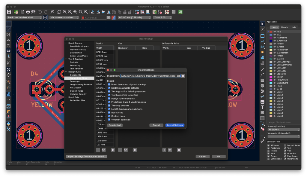
5. Import the Settings
- Click the “Import Settings from Another Board…” button (bottom-left corner)
- Navigate to the cloned repository folder
- Select one of the example files and click Import
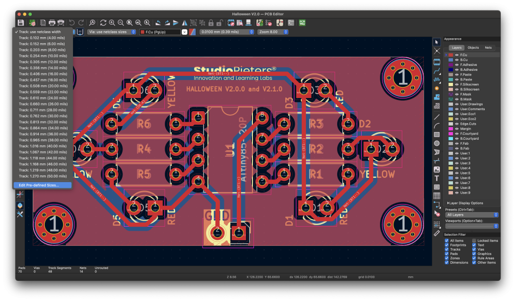
Now, while routing, you can simply right-click and choose from your custom list of predefined widths and vias.
Example Use Cases
Let’s say you’re working on a mixed-signal board with logic and power lines:
- Use 0.20 mm for standard logic signals
- Use 0.30 mm for short power traces
- Use 0.15 mm for densely packed areas or breakout boards
- Use 0.40 mm for battery or power input lines
Having these settings predefined makes routing much more intuitive and efficient.
Conclusion
KiCAD6-Trackwidth is a small but powerful improvement to your KiCad workflow. Whether you’re working on hobby projects or professional-grade hardware, this predefined set of track widths and vias will save you time and ensure consistent, clean designs every time.
Get started now by downloading the project on GitHub:
https://github.com/AchimPieters/KiCAD6-Trackwidth