A thermocouple is a device for measuring temperature. It comprises two dissimilar metallic wires joined together to form a junction. When the junction is heated or cooled, a small voltage is generated in the electrical circuit of the thermocouple which can be measured, and this corresponds to temperature.
Basics of Thermocouples
A thermocouple consists of two plates of different metals. Both plates are connected at one end and make a junction. The junction is placed on the element or surface where we want to measure the temperature. This junction is known as a hot junction. And the second end of the plate is kept at a lower temperature (room temperature). This junction is known as cold junction or reference junction. According to the Seebeck effect, the temperature difference between the two different metals induces the potential differences between two points of the thermocouple plates.
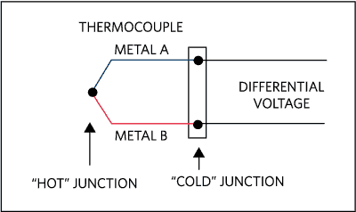
If the circuit is closed, a very small amount of current will flow through the circuit. A voltmeter is connected in the circuit. The voltage measured by the voltmeter is a function of a temperature difference between two junctions. Hence, by measuring the voltage, we can calculate the temperature of the hot junction.

Thermocouple Types
According to different types of combinations of alloys, the thermocouples are available in different types. The type of thermocouple is chosen according to the application, cost, availability, stability, chemical properties, output, and temperature ranges.
Type K Thermocouple
The K type thermocouple is the most common type of thermocouple, and it has the widest temperature measuring range. The positive lead of Type K thermocouple is composed of approximately 90% nickel and 10% chromium. The negative lead is composed of approximately 95% nickel, 2% aluminum, 2% manganese, and 1% silicon.

The positive lead is colored yellow and it is a non-magnetic material. The negative lead is colored red and it is a magnetic material. And the overall jacket is colored yellow. The temperature range of type K thermocouple is -200˚C to +1260˚C (-328 F to +2300 F). It is inexpensive and widely used in the general-purpose applications where temperature sensitivity requires approximately 41μV/˚C. The accuracy of type K thermocouple is ±2.2 C% (0.75%). The accuracy of thermocouple also depends on the deviation in alloys.
Thermocouple Amplifier MAX31855
Thermocouples are very sensitive, requiring a good amplifier with a cold-compensation reference. The MAX31855K does everything for you, and can be easily interfaced with any microcontroller, even one without an analog input. This breakout board has the chip itself, a 3.3V regulator with 10uF bypass capacitors and level shifting circuitry, all assembled and tested. Comes with a 2 pin terminal block (for connecting to the thermocouple) and pin header (to plug into any breadboard or perfboard).

Wiring a Thermocouple
The first thing to determine is which wire is which. As you remember, thermocouples are made by welding two wires together, the chip reads the voltage difference between the two. One is the negative (for K-type it is made of Alumel) and the other positive (ditto, Chromel). Fortunately the wires are color coded, and almost all the time you will find that the Alumel is red and the Chromel is yellow.
NOTE: The MAX31855 thermocouple amplifier is not compatible with grounded thermocouples.
NOTE: I’ve seen some K type thermocouples where the leads were marked incorrectly, so if you find that the thermocouple temperature goes down instead of up when heated, try swapping the red and yellow wires.
Code
First off, Vin and GND must connect to a 3-5V supply. Then the three data pins must connect to digital IO pins:
- CLK (clock) is an input to the MAX31855 (output from microcontroller) which indicates when to present another bit of data
- DO (data out) is an output from the MAX31855 (input to the microcontroller) which carries each bit of data
- CS (chip select) is an input to the MAX31855 (output from the microcontroller) which tells the chip when its time to read the thermocouple and output more data.
In the beginning of our sketches, we define these pins. For our examples DO connects to digital 3, CS connects to digital 4, and CLK connects to pin 5
If you are using the MAX31855 v1.0 in a noisy environment, you may need to add a 0.01uF capacitor across the thermocouple leads.
The MAX31855 does not support grounded thermocouples – if the sensor touches ground the chip will return an error

Arduino Library
If you have an older MAX6675 breakout, download the Adafruit MAX6675 library from the Arduino library manager.
If you have the newer MAX31855 breakout, download the Adafruit MAX31855 library from the Arduino library manager.
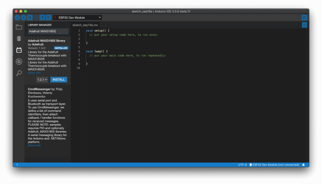
Open up the Arduino library manager:

If you have the MAX31855 breakout, search for the Adafruit MAX31855 library and install it.
Open up the File->Examples->MAX6675/Adafruit_MAX31855->serialthermocouple sketch and upload it to your Arduino. Once uploaded, open up the serial port monitor to display the current temperatures in both Celsius and Fahrenheit.

We also have a great tutorial on Arduino library installation at:
http://learn.adafruit.com/adafruit-all-about-arduino-libraries-install-use
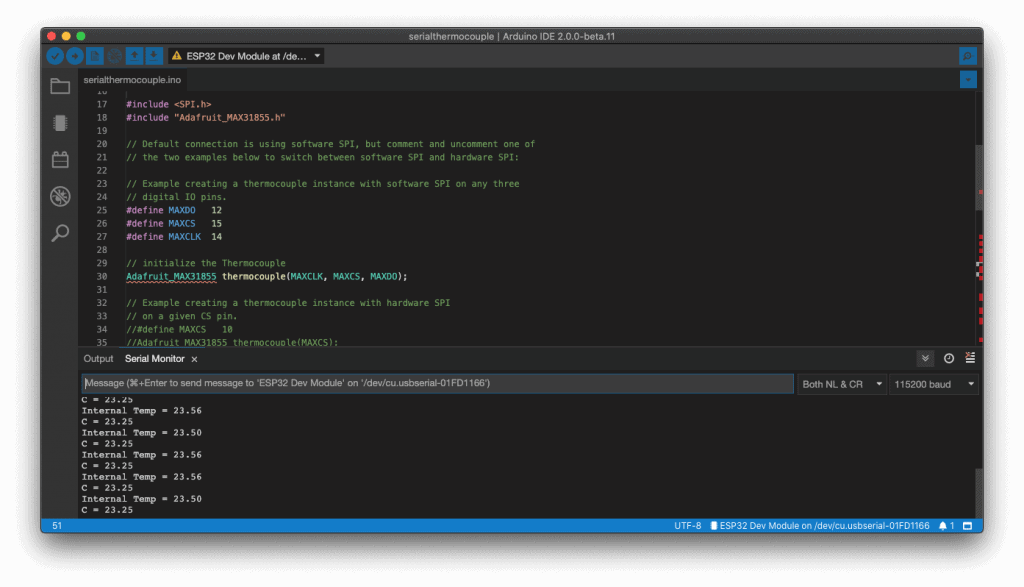
As you can see, its pretty simple to use the library, simply tell the sensor object what the clock, chip select and data pins are, then call readCelsius() or readFahrenheit() to get a floating point result.

Reference:
AspenCore, How to Play with Thermocouples, https://www.electroschematics.com/how-to-play-with-thermocouples ELECTRONOOBS, Temperature PID controller – Arduino, https://electronoobs.com/eng_arduino_tut24.php Adafruit, MAX31855 Thermocouple, https://learn.adafruit.com/thermocouple