The classic ATtiny85 is still a favorite among makers, but Microchip has since released a much more modern successor: the ATtiny 0-, 1-, and 2-Series. These new generation ATtiny chips combine higher performance, more peripherals, and a far more flexible architecture — all in the same compact form factor.
In this guide, you’ll learn what the ATtiny 0/1/2-Series are, how they differ from older chips like the ATtiny85, and why they’re often the better choice for your projects today.
What Are the ATtiny 0-, 1-, and 2-Series?
Modern AVR Microcontrollers
The ATtiny 0-, 1-, and 2-Series are 8-bit AVR microcontrollers based on the newer AVRxt CPU core, which is more efficient and powerful than the old ATtiny25/45/85 core. They run up to 20 MHz and include a much richer feature set.
Memory and Peripherals
Depending on the model, you’ll find:
- Flash memory: 2 KB to 32 KB
- SRAM: 128 B to 2 KB
- EEPROM: integrated into flash
- Timers: one powerful 16-bit TCA + multiple 16/8-bit TCB timers
- ADC: 10-bit or 12-bit (depending on the series)
- DAC: available on certain devices
- USART, SPI, I²C (TWI) with full hardware support
- Event System: route signals in hardware without CPU load
- Configurable Custom Logic (CCL): tiny programmable logic blocks built right in
Form Factor
These chips are available in DIP, SOIC, QFN, and WLCSP packages.
For hobbyists, the DIP-14 and DIP-20 versions are the most convenient — breadboard-friendly and far more powerful than the old DIP-8 ATtiny85.
Key Differences from the ATtiny85
| Feature | ATtiny85 (Classic) | ATtiny 0/1/2-Series (Modern) |
|---|---|---|
| CPU Core | Classic AVR | AVRxt (faster, more efficient) |
| Max Clock | 20 MHz | 20 MHz (more instructions/Hz) |
| Flash | 8 KB | 2–32 KB |
| SRAM | 512 B | 128 B – 2 KB |
| ADC | 10-bit | 10- or 12-bit |
| DAC | No | Yes (some models) |
| Timers | 2 | 3+ (advanced) |
| Peripherals | USI (SPI/I²C) | True USART, SPI, I²C |
| Debug | debugWIRE | UPDI (one-wire programming) |
| Power Range | 2.7–5.5 V | 1.8–5.5 V |
In short: the new series give you more memory, better peripherals, more powerful timers, and an easier programming interface.
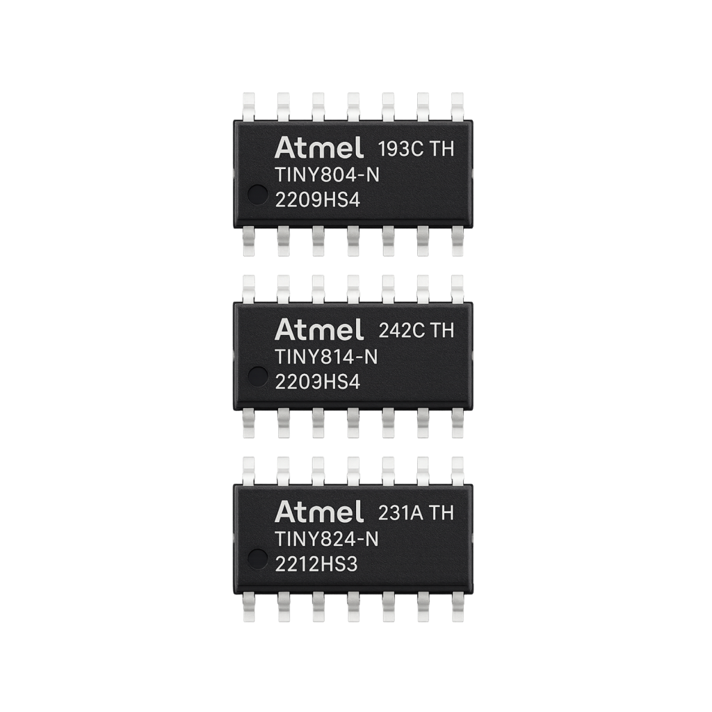
ATtiny 0-Series
The entry-level line.
- Up to 8 KB flash
- 10-bit ADC
- One USART
- No CCL (logic blocks)
Perfect for small projects where you’d normally reach for an ATtiny85 replacement.
ATtiny 1-Series
The “sweet spot.”
- Up to 16 KB flash
- 12-bit ADC
- Optional DAC
- CCL (Configurable Custom Logic) included
- Up to 2 KB SRAM
Great for sensors, LED drivers, smart I/O, and communication projects.
ATtiny 2-Series
The most advanced generation.
- Up to 32 KB flash
- Up to 3 USARTs
- 12-bit ADC
- DAC and CCL included
- More timers and richer peripherals
- Wider voltage support
The ATtiny 2-Series can handle complex projects that once required a larger ATmega328p or ATmega32u4.
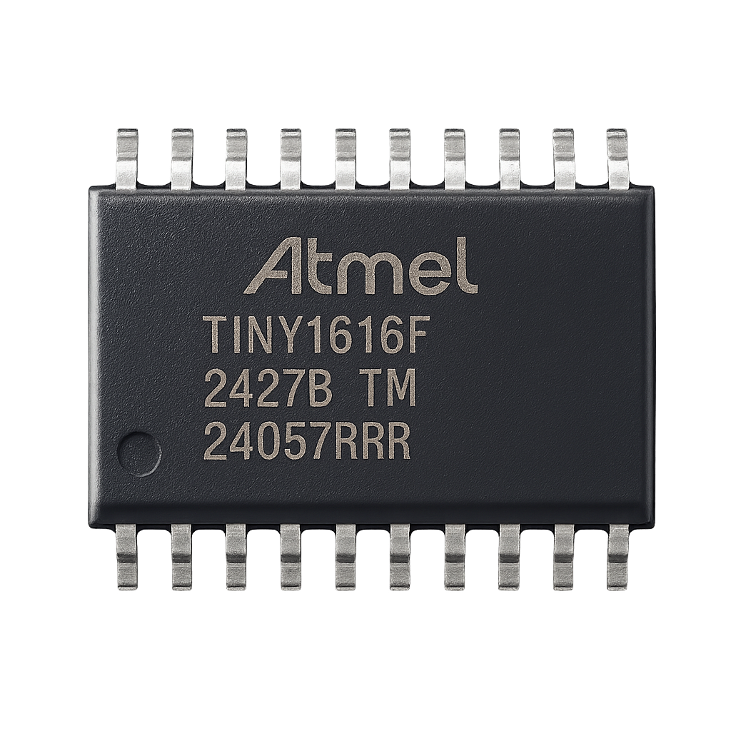
Example Pinout: ATtiny1616 (20-pin)
Complete Pin Function Table — ATtiny1616 (20-pin SOIC)
| Pin | Name | Functions |
|---|---|---|
| 1 | VCC (VDD) | Power supply (1.8 – 5.5 V) |
| 2 | PA4 | Analog (AIN4), Digital I/O, nSS (SPI slave select), CCL input (CCL0) |
| 3 | PA5 | Analog (AIN5), Digital I/O |
| 4 | PA6 | Analog (AIN6), DAC output, Digital I/O |
| 5 | PA7 | Analog (AIN7), Digital I/O, CCL output (e.g., CCL1) |
| 6 | PB5 | Analog (AIN8), Digital I/O |
| 7 | PB4 | Analog (AIN9), Digital I/O |
| 8 | PB3 | Analog (TOSC1), Digital I/O, TOSC (Timer oscillator) l |
| 9 | PB2 | Analog (TOSC2), Digital I/O, TOSC |
| 10 | PB1 | Analog (AIN10), SDA (I²C), Digital I/O |
| 11 | PB0 | Analog (AIN11), SCL (I²C), Digital I/O |
| 12 | PC0 | Digital I/O, PWM capable |
| 13 | PC1 | Digital I/O, PWM capable |
| 14 | PC2 | Digital I/O |
| 15 | PC3 | Digital I/O |
| 16 | PA0 | Analog (AIN0), Digital I/O, nRESET, UPDI |
| 17 | PA1 | Analog (AIN1), Digital I/O, MOSI (SPI), USART |
| 18 | PA2 | Analog (AIN2), Digital I/O, MISO (SPI) |
| 19 | PA3 | Analog (AIN3), Digital I/O, SCK (SPI), EXTCLK |
| 20 | GND | Ground |
Note: In the SOIC package, Pin 20 is GND—UPDI and programming functions are shared on PA0 (Pin 16)
Notes & Highlights
- UPDI & Reset Sharing: The programming and debugging interface (UPDI) is multiplexed with the PA0 pin, which also serves as the reset line.
- Analog Inputs (AIN): The ATtiny1616 features 12 analog input channels (AIN0–AIN11), spread across ports PA, PB, etc. r
- SPI Pins: Traditional SPI pins (MOSI, MISO, SCK, SS) are available on PA1 (MOSI), PA2 (MISO), PA3 (SCK), and PA4 (SS) respectively.
- Timers & Oscillators: PB3 and PB2 are used as dedicated TOSC pins for timer oscillation.
- PWM Capability: PC0 and PC1 are flagged as capable of PWM output.
UPDI – New Programming Interface
Instead of ISP or debugWIRE, the new ATtiny devices use UPDI (Unified Program and Debug Interface).
- Only 1 pin required (UPDI)
- Works with cheap USB-UPDI adapters or an Arduino as a programmer
- Supports both flashing and debugging
Power and Clock
- Voltage range: 1.8 V – 5.5 V
- Clock: internal 20 MHz oscillator (more accurate than older ATtinys)
- Sleep modes: ultra-low-power, ideal for IoT and battery-driven devices
How to Program the ATtiny 0/1/2-Series
I will explain step by step how to program an ATtiny 0/1/2-series chip (such as the ATtiny1616, ATtiny3216, etc.) using an Arduino Nano that you convert into a UPDI programmer with the help of jtag2updi.
What You Need
- Arduino Nano (Uno works too)
- ATtiny 0/1/2-series chip (for example, ATtiny1616)
- 4.7k Ω resistor (between Arduino and UPDI pin)
- Jumper wires / breadboard
- Arduino IDE (with megaTinyCore installed)
- Optional: SOP20 programmer
Step 1 – Prepare the Arduino Nano
- Connect your Arduino Nano via USB.
- Open the Arduino IDE.
- Download the jtag2updi firmware from GitHub:
https://github.com/ElTangas/jtag2updi - Open the
jtag2updi.inofile in the Arduino IDE and upload it to the Nano.
After this step, your Nano will no longer act as a normal Arduino — it is now a UPDI programmer.
Step 2 – Wiring
Connect the Nano to the ATtiny:
- Nano D6 → UPDI pin of the ATtiny (through a 4.7k Ω resistor)
- Nano GND → GND of the ATtiny
- Nano 5V (or 3.3V, depending on your chip) → VCC of the ATtiny
Important: Every ATtiny 0/1/2-series device has a UPDI pin (usually PA0). Always check the datasheet for the exact pin number of your device!
Simple wiring diagram:
Arduino Nano (UPDI programmer)    ATtiny1616
---------------------------------------------
D6  ----[4.7k]---->   UPDI (PA0)
GND  ---------------->   GND
5V   ---------------->   VCC (1.8 – 5.5 V)

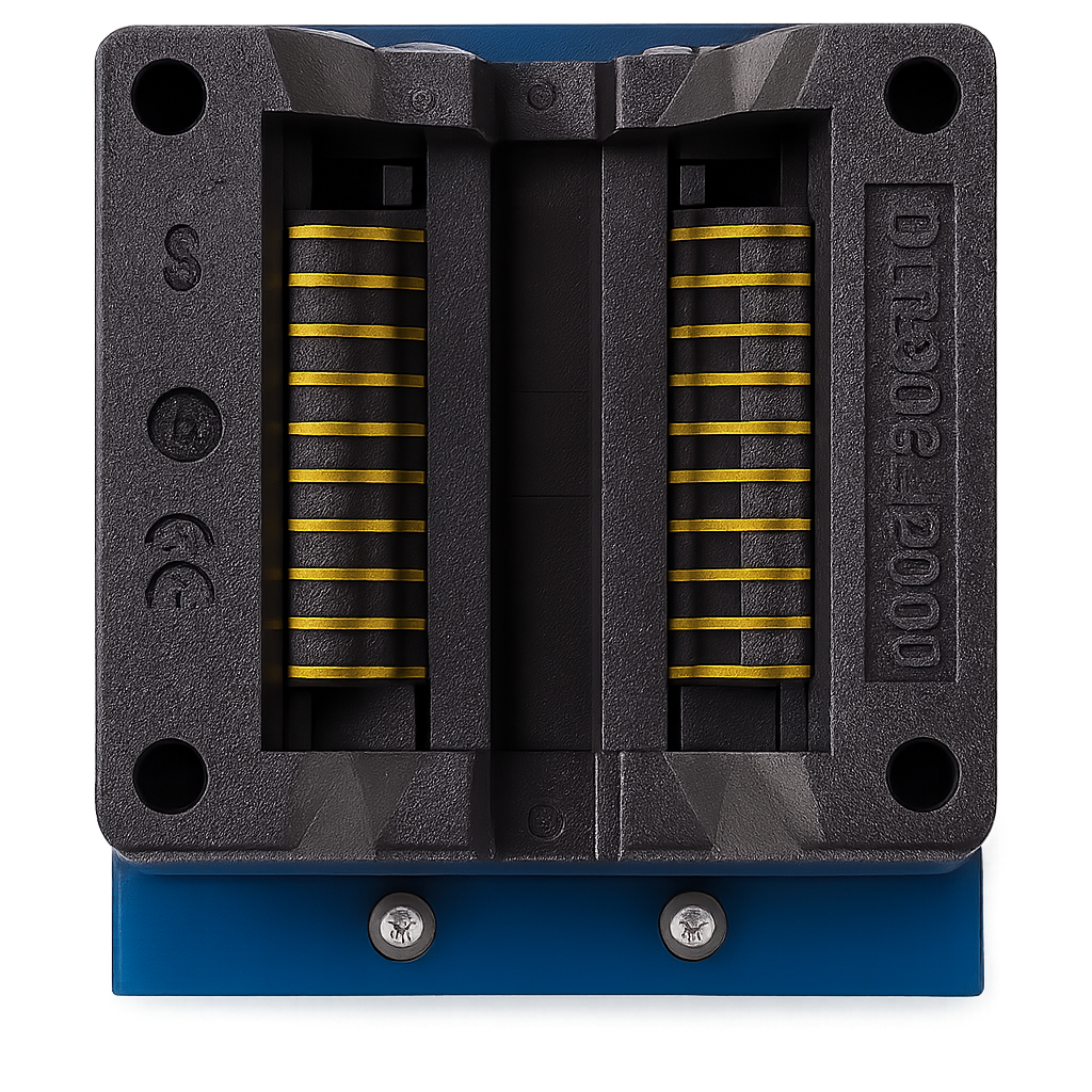
20-Pin SOP Programmer for Breadboard Prototyping
A 20-pin SOP (Small Outline Package) programmer adapter is a simple breakout board that lets you use surface-mount ATtiny1616 (or other ATtiny 0/1/2-series in SOIC-20) chips directly on a breadboard. Since the ATtiny1616 is only available in an SOIC-20 package and not in a classic DIP version, it can’t be plugged into a breadboard on its own. With this adapter, you can easily connect power, ground, I²C, SPI, UPDI, and GPIO pins to standard 2.54 mm headers, making it straightforward to prototype, test, and program the chip with an Arduino Nano + jtag2updi or a dedicated UPDI programmer.
Step 3 – Install megaTinyCore
- In Arduino IDE: go to File → Preferences
- Add this URL to Additional Boards Manager URLs:
http://drazzy.com/package_drazzy.com_index.json - Go to Tools → Board → Board Manager and install megaTinyCore.
Step 4 – Configure and Upload
- In Tools → Board, select ATtiny (megaTinyCore) and choose your chip (e.g. ATtiny1616).
- Under Programmer, select:
jtag2updi (megaTinyCore) - Write your sketch (for example, a simple blink).
- Click Upload Using Programmer.
Your code will now be uploaded from the Nano → UPDI → ATtiny!
Advantages
- Very low cost: you can simply reuse an Arduino Nano.
- Works reliably with almost all ATtiny 0/1/2-series chips.
Notes
- Don’t forget the 4.7k resistor — without it, you could damage the UPDI pin.
- Use the correct supply voltage (some ATtiny chips are 3.3V only at higher speeds).
Best Practices and Tips
- Always include a UPDI header on your PCB – even for production units
- Check the datasheet for pin multiplexing when combining peripherals
- For low-power projects: disable unused peripherals and use sleep modes
- The internal oscillator is usually accurate enough – no external crystal needed
- The ATtiny 1-Series (e.g., ATtiny1616) is the best balance of features vs. simplicity
Conclusion: The Modern ATtiny
The ATtiny 0-, 1-, and 2-Series are the true successors to the classic ATtiny85. They are:
- Smaller in power consumption
- Bigger in features
- Easier to program and debug
For small but powerful projects, these are the chips you’ll want to use in 2025. Whether you’re building a wearable, IoT sensor, or LED installation, there’s a modern ATtiny that fits your needs.