Servo motors can be found in robotic arms, cameras, lathes, CNC machines, printing presses and other engineering applications where precision and repetitive motion are required. Servo motors often consist of DC motors that use feedback mechanisms to move from one position to another with great precision. The inexpensive servos found in maker projects use potentiometers to register voltages as positions on the servo’s rotating face. Often servo motors contain a series of gears that speed up or slow down and facilitate the movement of the DC motor. Finally, servo motors use a circuit to control and send feedback information to a particular controller.

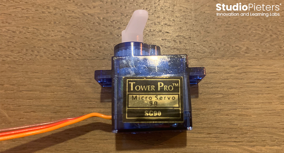
Tower Pro™ Micro servo S9 (SG90)
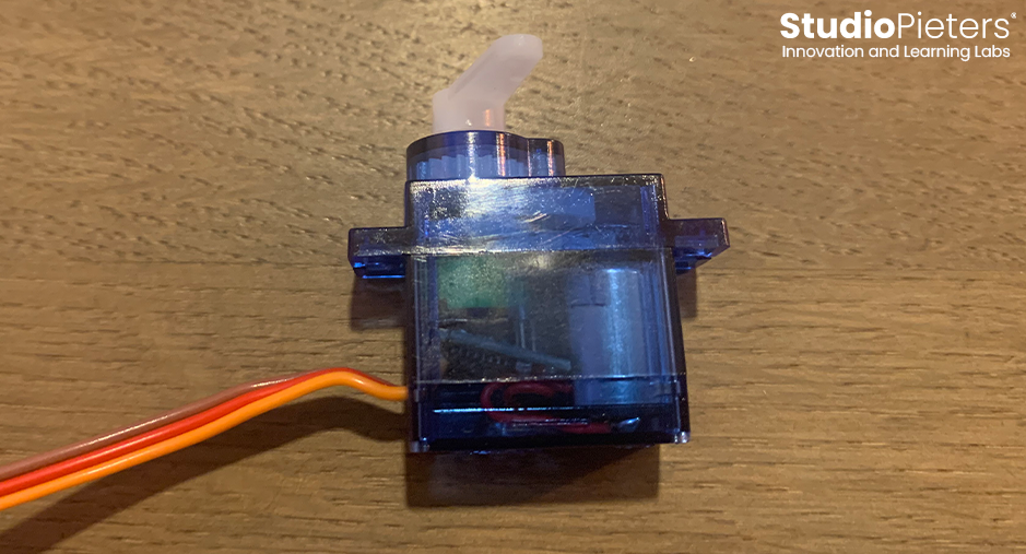
The SG90 is a 9 gram servo motor that can rotate 0 – 180 degrees (roughly) at a speed of about 0.3 seconds (0.1 s/60 degrees). The SG90 is used in low cost projects, mostly with motorized vehicles and robotic arms. The SG90 is a great tool for education and prototyping – because it’s cheap and easy to use. The SG90 is also compatible with the Arduino software, which will be used in this tutorial to rotate the servo to see how the gear reduction from the small DC motor gear to the larger and slower gear is used in motor-driven applications.
In this animation is shown the process of the gear reduction, with the DC motor being driven through a gear reduction stage, with a stabilizing gear stage (the center pole in the image above showing the motor and potentiometer), and finally the slower rotating gear used for applications (the top gear). The video shows the SG90 under 5.0V powered by an Arduino board, rotating 1 degree for 90 degrees and then stopping.
Modification
We are going to take a regular servo and convert it to a continuous rotation servo. You may see a lot of tutorials like this on YouTube and a few are really good and a few are terrible. I also want to discuss exactly what the differences and some styles are and explain why you do the things you do. Not every servo is the same and not everyone has the same tools and depending on the tools you have on hand you can approach this differently. So we’re going to try to make it a little less vague while still being very specific about exactly how to do it.
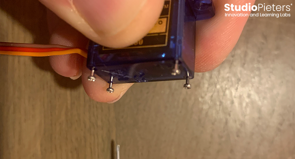
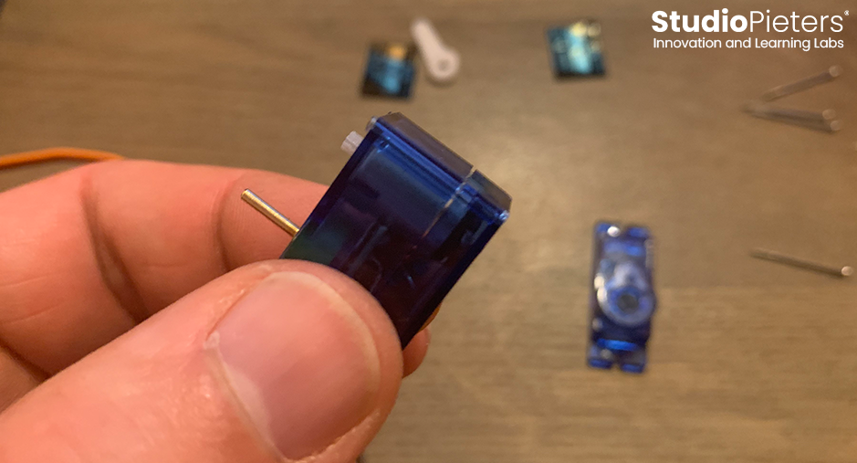
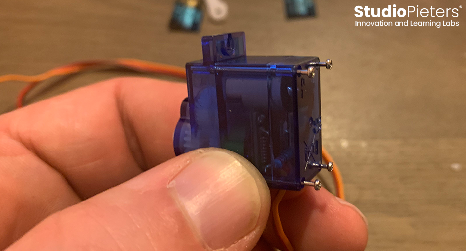
The first step is to remove the screws on the back. While you’re removing them, don’t try to pull the back off just yet, because we have one more thing to do before we take everything apart.
Now that the screws are removed, let’s grab an a corner of the sticker and remove it on both sides.
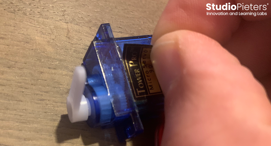
Your Servo should now look like this.
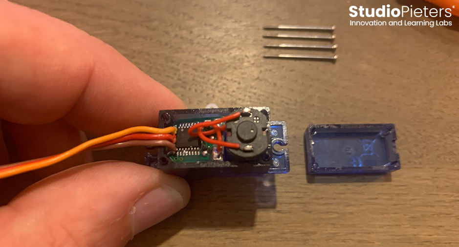
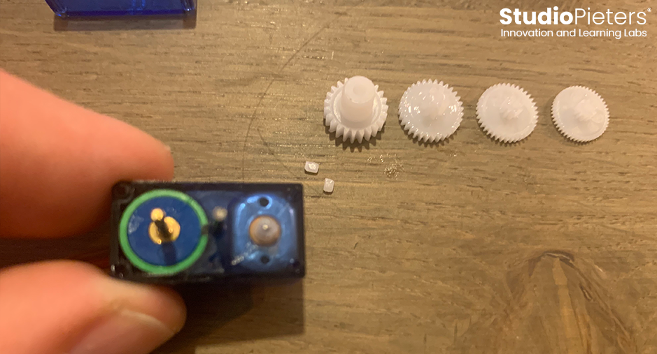
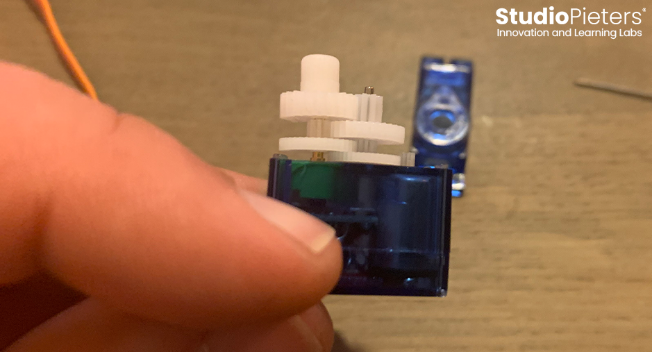
Now you can take the top and bottom off. We now have the engine and this is what runs down and spins the gears. But this is controlled by a little control board. That board is what talks to the potentiometer sitting right behind the grears and is trying to say, “Hey, where am I now? And where am I supposed to be?” What we have to do, is we have to make some adjustments to that board.

On this other side we see the different gears, and here we have to worry about the physical aspects.
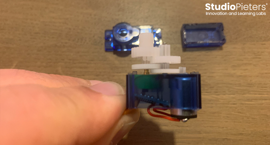
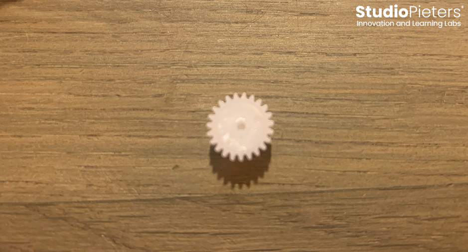
When it spins it changes the signal. The potentiometer is rotated by a top gear. Remove the top gear. As you can see there is a flat piece that turns the potentiometer.
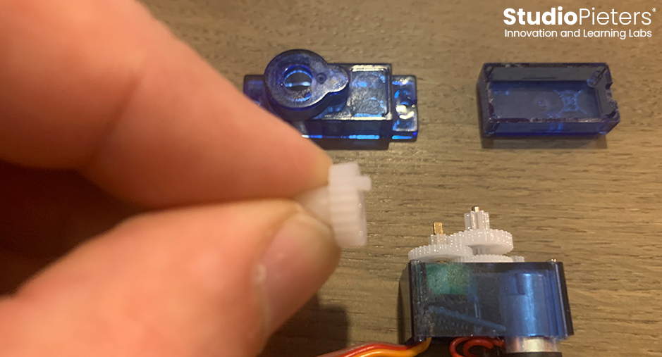
We’re going to have to make some adjustments to this Gear so that it doesn’t actually turn the potentiometer, and remove the stop so you can’t turn more than 180 degrees.
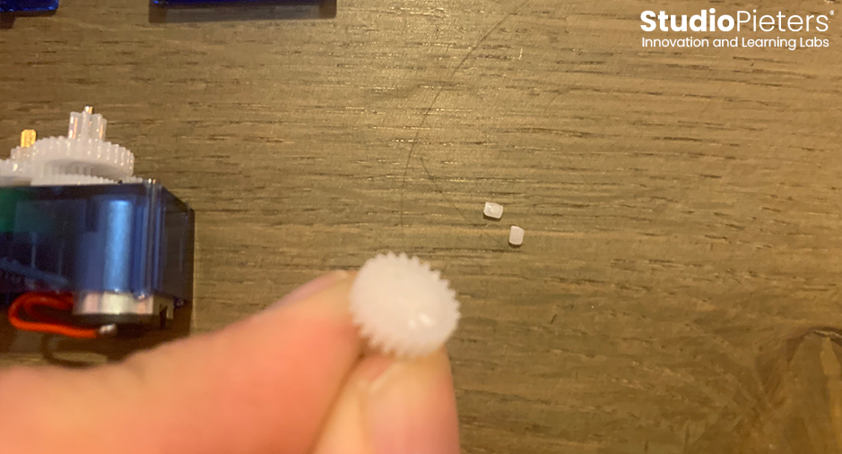
Remove all gears. Tip: put them in the order you removed them, then it’s easier to put it back together afterwards!

Replacing the Potentiometer
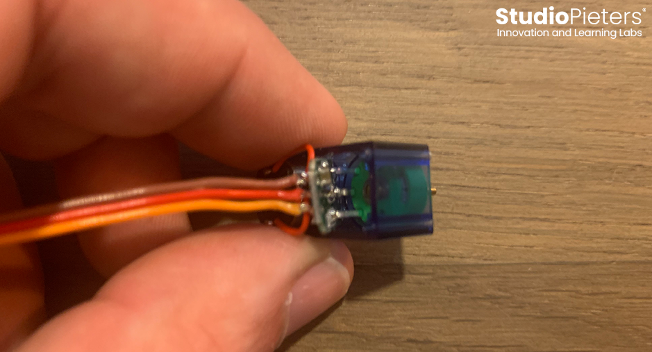
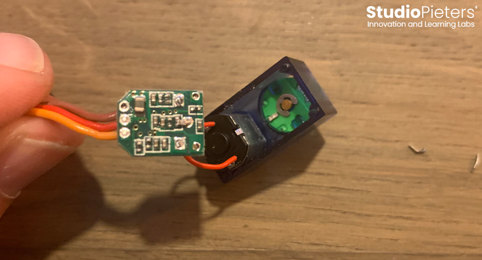
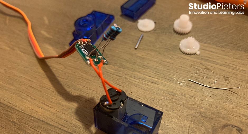
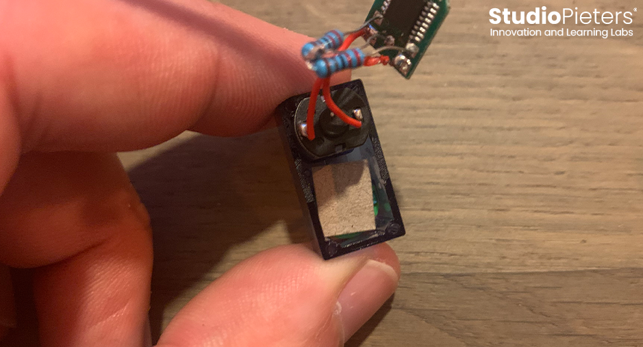
Very carefully pull the PCB forward as shown in the picture. As you can see the potentiometer is soldered directly to the PCB. Cut /desolder the connections between the PCB and the Potentiometer. If you have really thin snippers or clippers or something that you can get down there, that’s great. I don’t and so I actually use forceps to twist and break the wire. It is a bit ugly and it works extremely well sometimes and other times not very well. But it’s a lot better than trying to get in there with something else to cut it. So you can just grab the wire, wiggle back and forth until it breaks.

Now that you can see all three leads are broken. Once that is done you should have something like this.
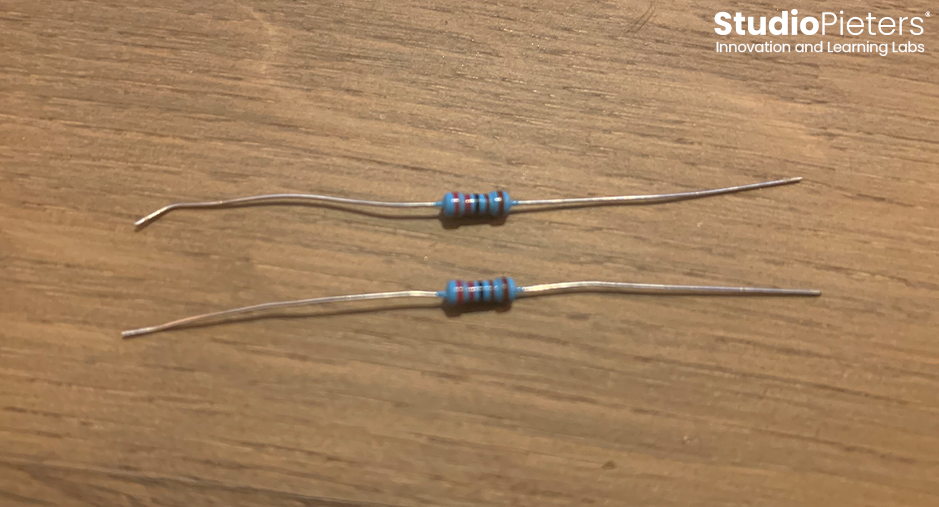
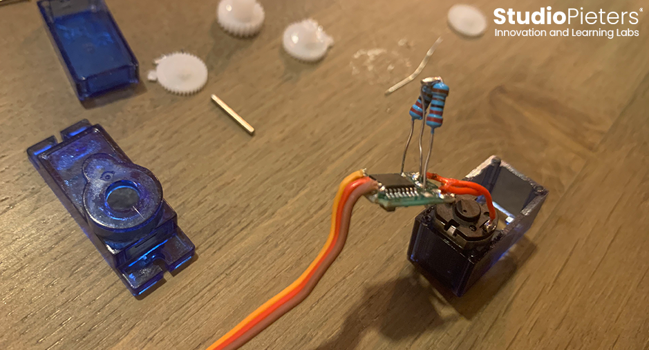
At this point, you need to solder the two resistors on. to determine the value of the resistors, you need to know the value of the Potentiometer. You can remove the potentiometer from the servo housing and measure it with a multimeter. Divide the value by two and you have your resistance value.
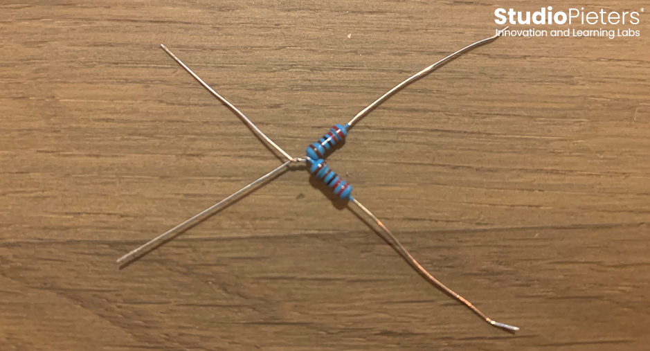
Twist the resistors together on one side.
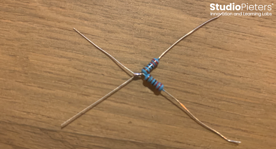
Solder the resistors together.
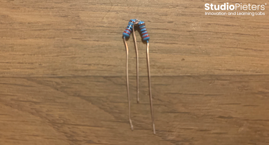
Remove one leg, leaving three, as shown in the image below.
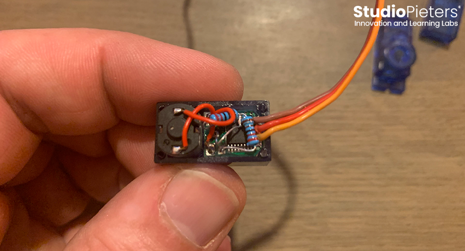
Solder the resistors where the potentiometer was soldered.
The main point of this is to make sure that the input to the driver thinks that it’s always in the middle and so when you send it a signal to say, “hey, go to this direction”, it’s going to keep on going until you tell it to stop because it’s never gonna receive the feedback signal that it’s actually reached its destination.

we need to drill out the part that fits tightly on the potentiometer shaft. I use a cordless drill for this. Now you should see that the grear is completely flat where the stopper used to be and that you made the hole round where the flat piece grabed the potentiometer. It should fit snugly back onto the shaft and rotate freely even with the top back on.
Here is an example of putting on the little pieace of cardboard. Again, the idea is to make it so that as you put the board back in, it doesn’t accidentally touch the terminals of the potentiometer and cause some problems.
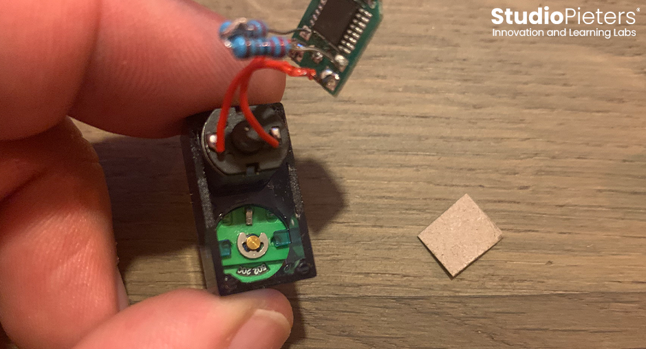
Just palce the cardboard like this, or just glued it in place, then you don’t need to worry about this.
With that, we are good to put this back together. Get the board back into position.

put the bottom back on and see if everything fits properly back into the housing.
Put the gears back in their correct position
replace and tighten the screws. Tip: Tighten the screws when you put it together but make it snug, not overly tight.
That’s it! Now we have gotten rid of the physical things that were stopping the servo from turning all the way around. We disconnected it from the potentiometer because we don’t have anything to center the potentiometer. We had to cut it out of the circuit and instead put two resistors to create that voltage divider to replace the potentiometer and now it should be good to go.
Testing
And that’s it! Hopefully that was clear. If you have any questions, leave it in the comments below.

Reference:
Instructables, How to Modify a Micro Servo Motor, https://www.instructables.com/How-to-Modify-a-Micro-Servo-Motor-SG90-for-Continu CircuitBread, How to make a 360 degree Continuous Rotation Servo Motor, https://www.circuitbread.com/tutorials/how-to-make-a-360-degree-continuous-rotation-servo-motor