In the world of Internet of Things (IoT) and embedded systems, the ESPC2-02 Module stands out as a powerful and versatile tool for developers and hobbyists alike. Whether you’re a seasoned programmer or just dipping your toes into the world of electronics, this compact yet feature-rich module offers a gateway to endless possibilities. In this blog, we’ll dive into what the ESPC2-02 Module is all about and how you can get started with programming it using a breadboard, an FT232RL module, two push buttons, and two 10K ohm resistors.
Understanding the ESPC2-02 Module
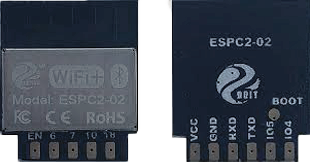
The ESPC2-02 Module is a Wi-Fi enabled microcontroller module based on the ESP8266 chipset. It comes equipped with built-in Wi-Fi capabilities, GPIO pins for interfacing with external components, and support for programming using various development environments such as the Arduino IDE and MicroPython. With its low cost and ease of use, it has become a popular choice for IoT projects, home automation, and prototyping.

Getting Started with Programming
To begin programming the ESPC2-02 Module, you’ll need the following components:
- ESPC2-02 Module
- Breadboard
- FT232RL module (USB to Serial converter)
- Two push buttons
- Two 10K ohm resistors
- Jumper wires
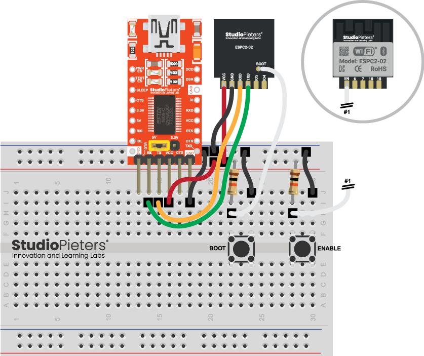
Step 1: Connect the FT232RL Module to the ESPC2-02 Module
Start by connecting the FT232RL module to the ESPC2-02 Module. The FT232RL module acts as a bridge between your computer and the ESPC2-02 Module, allowing you to program it via USB.
- Connect the TX pin of the FT232RL module to the RX pin (receive) of the ESPC2-02 Module.
- Connect the RX pin of the FT232RL module to the TX pin (transmit) of the ESPC2-02 Module.
- Make sure to connect the ground (GND) pins of both modules together.
The EN (Enable) and BOOT pins on the ESPC2-02 Module play crucial roles in programming and booting the module. Understanding how to use these pins and the correct sequence for programming is essential for successful interaction with the module.

EN (Enable) Pin:
The EN pin is used to enable or disable the ESPC2-02 Module. It acts as a power control pin. When pulled HIGH, the module is enabled and ready to operate. When pulled LOW, the module goes into a low-power state or is completely shut down.
BOOT Pin:
The BOOT pin is used during the programming (or flashing) process of the ESPC2-02 Module. It determines whether the module boots into normal operational mode or into firmware flashing mode. When the BOOT pin is pulled HIGH during power-up or reset, the module enters firmware flashing mode, allowing you to upload new firmware or code. Conversely, pulling the BOOT pin LOW during power-up or reset causes the module to boot into normal operational mode.
Programming Sequence:
To program the ESPC2-02 Module successfully, follow this sequence:
- Prepare Your Hardware: Ensure that your ESPC2-02 Module is properly connected to your programming interface (such as an FT232RL module or a USB-to-serial converter) and any necessary peripherals (such as push buttons or sensors) on your breadboard.
- Set the EN Pin: Make sure that the EN pin is pulled HIGH to enable the module. This allows the module to receive power and operate normally.
- Set the BOOT Pin: Depending on whether you want to enter firmware flashing mode or normal operational mode, set the BOOT pin accordingly:
- To enter firmware flashing mode, pull the BOOT pin HIGH.
- To boot into normal operational mode, leave the BOOT pin unconnected or pull it LOW.
- Power Up or Reset: Apply power to the ESPC2-02 Module by connecting it to a power source or resetting it. The module will boot according to the state of the BOOT pin:
- If the BOOT pin is pulled HIGH, the module will enter firmware flashing mode.
- If the BOOT pin is left unconnected or pulled LOW, the module will boot into normal operational mode.
- Programming: Once the module is in firmware flashing mode, you can proceed to upload new firmware or code using your preferred development environment (such as the Arduino IDE or esptool).
- After Programming: After programming is complete, you can reset the module by power-cycling it or by pulling the EN pin LOW and then back HIGH to restart it. Ensure that the BOOT pin is set to the desired mode for normal operation.
By following this sequence, you can effectively use the EN and BOOT pins on the ESPC2-02 Module to control its operation and program it as needed. Understanding the roles of these pins and their correct usage is essential for smooth development and debugging of projects involving the ESPC2-02 Module.