The ESP8266 is a classic microcontroller that has powered the IoT revolution. Praised for its affordability, integrated Wi-Fi, and robust community support, the ESP8266 is the go-to choice for tinkerers, students, and engineers building everything from smart switches to wireless sensors. In this guide, you’ll learn everything about the ESP8266 pinout.
What is the ESP8266?
System-on-Chip (SoC)
At its core, the ESP8266 features a compact and efficient SoC developed by Espressif Systems. With a single-core Tensilica L106 processor running at 80/160 MHz, integrated Wi-Fi, and enough RAM/flash support for advanced projects, the ESP8266 balances power, cost, and flexibility.
Module
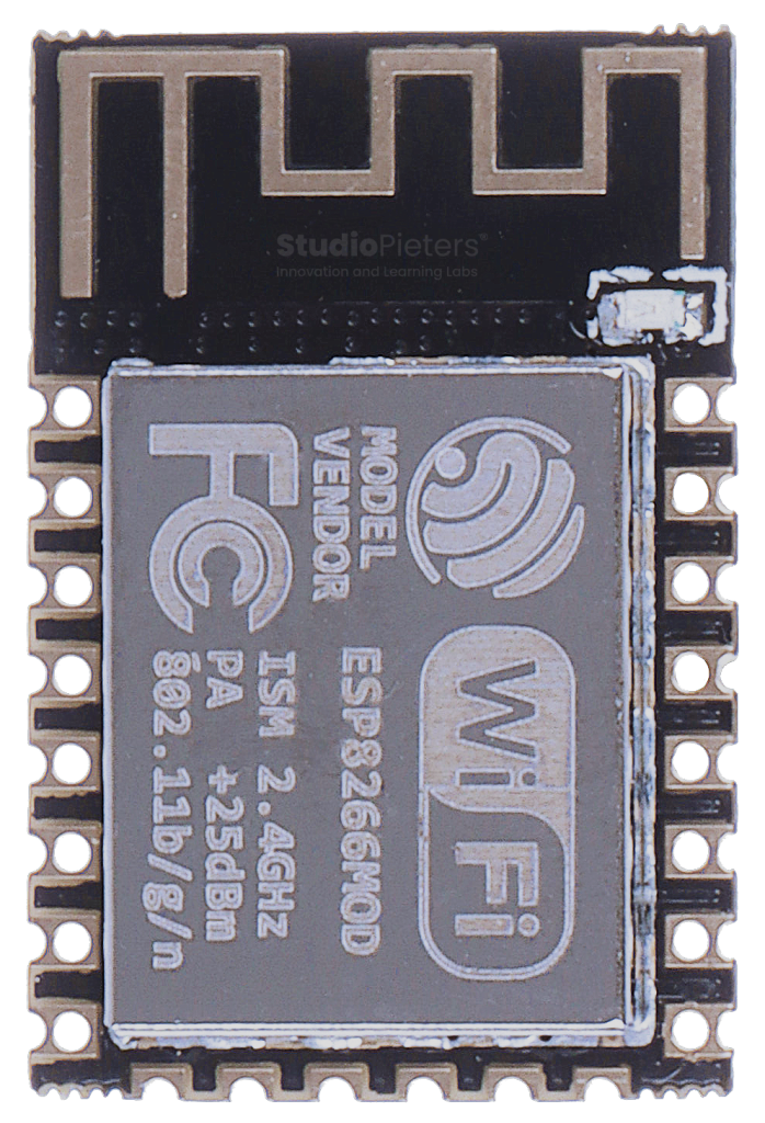
The most common module — ESP-12E (or ESP-12F) — houses the ESP8266 chip, flash memory, and a metal shield, all in a tiny package that’s easily embeddable in your projects.
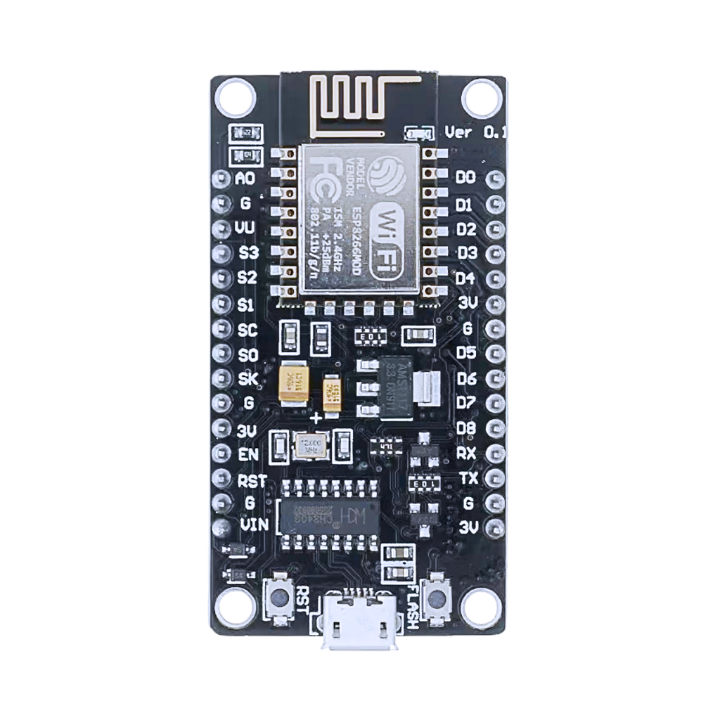
Development Board (NodeMCU, Wemos D1 Mini)
To make life even easier, the ESP8266 is available on dev boards like the NodeMCU and Wemos D1 Mini. These boards add USB, voltage regulation, reset/flash buttons, and break out all usable pins for fast prototyping.
Designed for Wireless Innovation
The ESP8266’s Wi-Fi capabilities are at the heart of its success, but the chip also features a healthy set of GPIOs, ADC, PWM, and serial interfaces.
Key Features:
- Wi-Fi 802.11 b/g/n (2.4GHz, WPA2)
- 17 GPIOs (varies by module/board)
- 1 × 10-bit ADC
- SPI, I2C (software), UART
- PWM on all GPIOs
- Deep Sleep (low power)
- Integrated TCP/IP stack
With these features, the ESP8266 easily powers smart home projects, wireless sensors, automation controllers, and more.
ESP8266 Pinout Diagram High Resolution

You can download a high-resolution ESP8266 pinout at the end of this post — completely free!
ESP8266 Pinout – GPIO Fundamentals
The ESP8266 exposes several GPIOs, but not all are created equal. Some are essential for boot or have unique behaviors. Below is everything you need to know.
Input and Output Pins
Most GPIOs support both digital input and output. PWM is available on all except GPIO16. There is a single analog input.
GPIO Mapping
- NodeMCU: Labeled as D0, D1, etc. (D0 = GPIO16, D1 = GPIO5, …)
- Wemos D1 Mini: Uses the same mapping as NodeMCU
- ESP-12E/F module: Pin numbers refer to the bare chip
Commonly Used GPIOs
| Board Label | Chip Pin | Special Functions |
|---|---|---|
| D0 | GPIO16 | Deep sleep wake-up |
| D1 | GPIO5 | SCL (I2C) |
| D2 | GPIO4 | SDA (I2C) |
| D3 | GPIO0 | Boot mode (must be high) |
| D4 | GPIO2 | Boot mode (must be high) |
| D5 | GPIO14 | SPI CLK |
| D6 | GPIO12 | SPI MISO |
| D7 | GPIO13 | SPI MOSI |
| D8 | GPIO15 | Boot mode (must be low) |
| RX | GPIO3 | UART RX |
| TX | GPIO1 | UART TX |
| A0 | ADC0 | 10-bit ADC input (0–1V) |
Boot-Related Pins
- GPIO0: Must be HIGH on boot. LOW to enter programming mode (flash mode).
- GPIO2: Must be HIGH on boot.
- GPIO15: Must be LOW on boot.
- EN (CH_PD): Must be HIGH (3.3V) for normal operation.
- RST: Pull LOW to reset.
Tip: Incorrect states on these pins can prevent normal booting!
ADC (Analog to Digital Converter)
- ADC0 (A0): Reads voltages from 0–1V only (on bare ESP-12E/F).
- Some boards include a voltage divider to accept up to 3.3V on A0.
Applications: Battery sensing, analog sensors, potentiometers.
I2C Communication
The ESP8266 supports I2C via software (bit-banged). Pins are user-assignable.
- Default: D1 (GPIO5, SCL), D2 (GPIO4, SDA)
- Applications: Sensors (BME280), displays (OLED), real-time clocks.

SPI Communication
Hardware SPI is available on:
- CLK: GPIO14 (D5)
- MISO: GPIO12 (D6)
- MOSI: GPIO13 (D7)
- CS: GPIO15 (D8)
Applications: SD cards, displays, fast sensors.

UART Communication
- UART0: GPIO1 (TX), GPIO3 (RX)
- UART1: TX-only, usually for debug output (GPIO2)
Applications: Serial monitor, GPS modules, wireless modules.
PWM
PWM is available on all GPIOs except GPIO16.
- Applications: LED dimming, servo control, motor speed regulation.
Interrupt Support
All GPIOs except GPIO16 can be used for interrupts (CHANGE, RISING, FALLING).
ESP8266 GPIO Quick Reference Table
| GPIO | NodeMCU/Wemos | Input | Output | ADC | PWM | I2C | SPI | UART | Boot | Notes |
|---|---|---|---|---|---|---|---|---|---|---|
| 0 | D3 | Yes | Yes | No | Yes | Yes | SS | Must be HIGH on boot | ||
| 1 | TX | Yes | Yes | No | Yes | TX | UART0 TX | |||
| 2 | D4 | Yes | Yes | No | Yes | Yes | Must be HIGH on boot | |||
| 3 | RX | Yes | Yes | No | Yes | RX | UART0 RX | |||
| 4 | D2 | Yes | Yes | No | Yes | SDA | ||||
| 5 | D1 | Yes | Yes | No | Yes | SCL | ||||
| 12 | D6 | Yes | Yes | No | Yes | MISO | ||||
| 13 | D7 | Yes | Yes | No | Yes | MOSI | ||||
| 14 | D5 | Yes | Yes | Noo | Yes | CLK | ||||
| 15 | D8 | Yes | Yes | No | Yes | SS | Must be LOW on boot | |||
| 16 | D0 | Yes | Yes | No | No | Deep sleep wake-up | ||||
| A0 | A0 | Yes | No | Yes | No | 0–1V input only* |
*Check if your board adds a voltage divider to A0 for 3.3V support.
Best Practices and Common Mistakes
Optimize your ESP8266 projects with these tips:
- Boot Pins: Don’t connect buttons/LEDs to GPIO0, GPIO2, or GPIO15 without understanding their boot requirements.
- ADC Voltage: Don’t exceed 1V on ADC0 unless your board has a divider.
- Power Supply: Always use a stable 3.3V supply — the ESP8266 is not 5V tolerant.
- Current Limits: Limit output current to ~12mA per GPIO.
- Deep Sleep: Use GPIO16 to wake from deep sleep (connect GPIO16 to RST).
- Pull-Ups/Downs: Use external pull-ups/downs for noisy or floating inputs.
- Serial Flashing: Enter flash mode by holding GPIO0 LOW during reset.
- Avoid Overloading: Don’t drive high-power loads directly from the GPIOs.
- Debounce Inputs: Always debounce button inputs in software or hardware.
How to Program the ESP8266
Development Environments
- Arduino IDE (most popular, beginner-friendly)
- PlatformIO (powerful, VSCode integration)
- NodeMCU Lua (interpreter-based)
- AT Command firmware (for basic Wi-Fi/serial tasks)
Programming Pins
| Function | Pin | Description |
|---|---|---|
| TXD0 | GPIO1 | ESP8266 to PC (output) |
| RXD0 | GPIO3 | PC to ESP8266 (input) |
| EN/CH_PD | EN | Chip enable (active HIGH) |
| GPIO0 | GPIO0 | Pull LOW to enter flash mode |
| RST | RST | Pull LOW to reset |
Programming Steps
- Connect ESP8266 to PC via USB (using NodeMCU/Wemos or serial adapter).
- Hold GPIO0 LOW, press RST (if needed) to enter flash mode.
- Select correct board/port in IDE.
- Upload your code with a single click.
- Most dev boards handle boot selection automatically — no need for button gymnastics!
Conclusion: Still a Wireless Classic
The ESP8266 is a true classic in the world of wireless microcontrollers. Its mix of simplicity, community resources, and reliable Wi-Fi makes it a perfect entry point for IoT and embedded development. Understanding the ESP8266 pinout is the foundation for stable, scalable projects — whether you’re building smart sensors, connected relays, or wireless gadgets.
Happy Building!Happy Building!
Download the ESP32 pinout here in high resolution – for free*!
* Free to use under the MIT license — attribution is required.