
HomeKit
ESP8266 HomeKit Blinds
* This project is featured on Instructables
- ESP8266
- HomeKit
- 7 min read
*This project is featured on Instructables
Motorized, HomeKit-controlled window blinds, built around an ESP8266 and a real stepper driver instead of a cheap RC servo. Out of every HomeKit accessory on this site, this one took the most attempts to get right, blinds need enough torque to actually pull fabric or slats up, and enough control to stop exactly where you tell them to.
HomeKit’s own Window Covering accessory type covers a lot of ground: roller blinds, Venetian blinds, curtains, Roman blinds, slats, pleated curtains, even outside blinds. They all have one thing in common, they need a motor to open and close, and that motor needs to survive being told to stop wherever HomeKit says to.
What You'll Build
By the end of this guide you’ll have a set of window blinds you can open, close, and stop mid-travel from the Apple Home app or with Siri, no separate remote, no cloud account, no subscription. It’s a bigger build than most of the HomeKit accessories on this site: real soldering, a stepper driver instead of a single relay, and a one-time calibration step so the accessory actually knows where “open” and “closed” are.
This guide is written for beginners. If you’ve never flashed an ESP8266 before, that’s fine, every command you need to type is spelled out below.
Difficulty Level
Rating: 3 / 5 Soldering Irons, comfortable beginner project, but the trickiest one on this site to get running the first time.
No advanced electronics background is required, but you should be comfortable with:
- Basic soldering (wiring a stepper driver, no surface-mount work)
- Typing commands into a Terminal window
- Being patient through a bit of trial and error, this project genuinely took several tries to get right, see below
Why This Took a Few Tries
Before settling on the final hardware, several stepper motors were tried and rejected, worth knowing up front so you don’t repeat the same dead ends:
- A 28BYJ-48 (5V) stepper was the first attempt. It didn’t work.
- A 28BYJ-48 (12V) was tried next. It also didn’t perform as it should.
- A Nema 17 was considered, but there was no library for driving a real stepper motor under ESP-Open-RTOS at the time, nobody seemed to have written one in C (a few Arduino/C++ examples existed, but they relied on standard Arduino libraries that don’t exist in this environment).
After building stepper control for ESP-Open-RTOS from scratch, a Nema 17 was tested for real, strong enough to pull the blinds, but with a real downside: with no power on the coils, the motor’s shaft spins freely, so the blinds come crashing back down once you let go after pulling them up. A PM42S-48 stepper was tried next for the same reason, smaller, with a decent amount of torque, but the exact same free-spinning problem when unpowered.
The build that finally worked went back to the 28BYJ-48 (12V), once stepper control actually worked correctly in ESP-Open-RTOS. A quick note on why the motor choice matters at all: uni-polar steppers like the 28BYJ-48 aren’t as efficient as bipolar steppers (two out of four coil wires sit unused at any given moment, even in full-step mode), but a 28BYJ-48 wired correctly turned out to be simple enough, and reliable enough, to finally get this project working end to end.
What You Need
Hardware:
- Node MCU V3 Lua ESP-12E WiFi development board
- DRV8825 Stepper Motor Driver module (an A4988 driver works too, its pinout is nearly identical, and can be used as a drop-in replacement)
- 28BYJ-48 (12V) stepper motor
- A physical up/down push button for calibration
- An FTDI/USB-serial adapter, if your board doesn’t already have one built in
- Soldering iron + wires
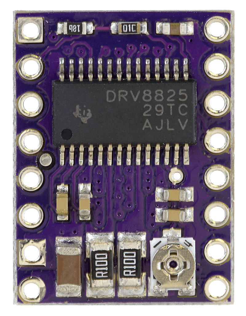
The DRV8825 is a Texas Instruments micro-stepping bipolar stepper motor driver breakout board with adjustable current limiting, over-current and over-temperature protection, and six micro-step resolutions, down to 1/32-step. It runs from 8.2V to 45V and can deliver roughly 1.5A per phase without a heatsink (up to 2.2A per coil with proper cooling), comfortably enough for a 28BYJ-48.
Wiring: NodeMCU + DRV8825
The wiring here is a bit more involved than a typical single-relay HomeKit accessory on this site, the DRV8825 needs its own step/direction lines from the ESP8266, plus power for the stepper motor itself, separate from the ESP’s own 3.3V supply.
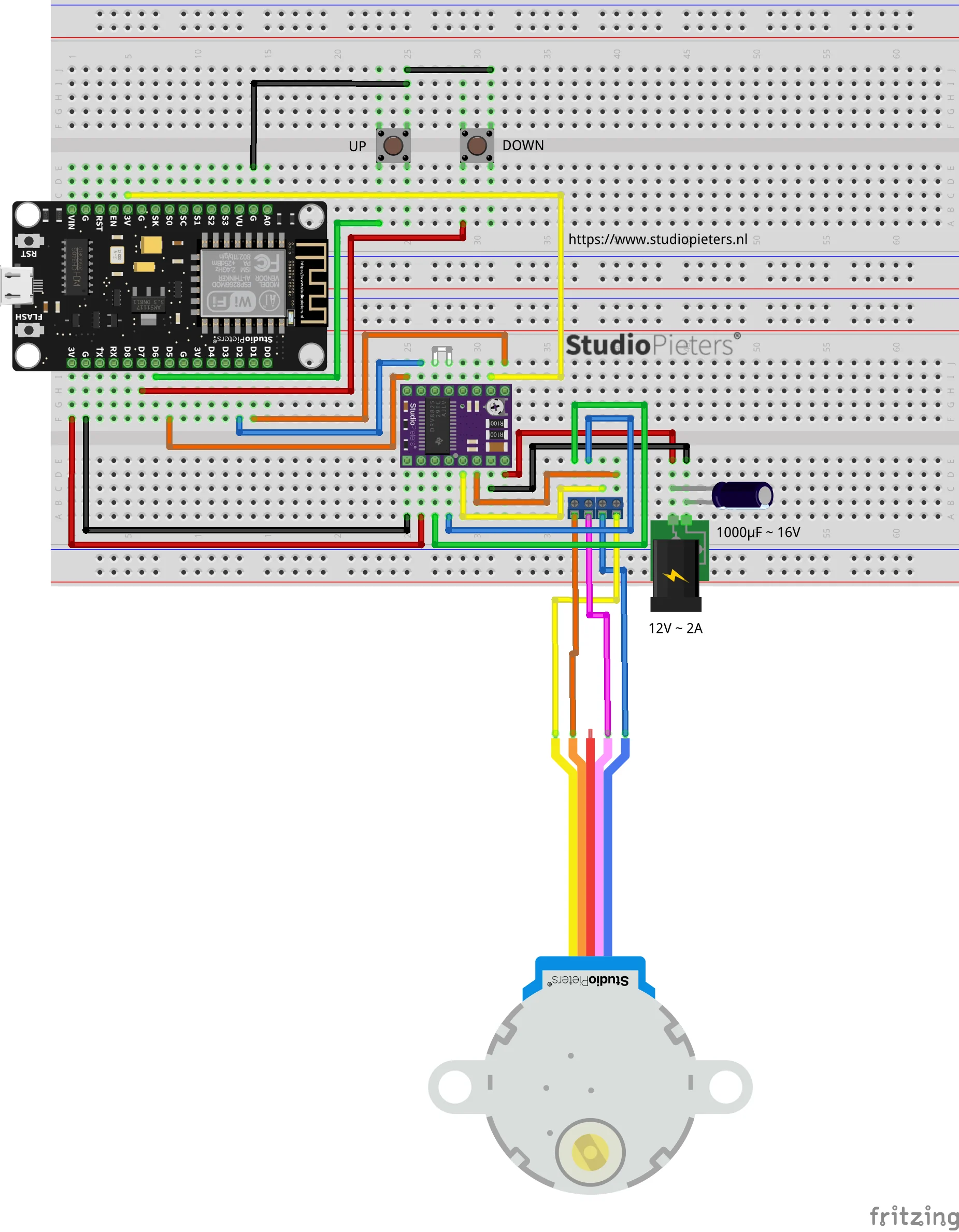
Double-check your DRV8825’s current limit (via its onboard trim-pot) against your 28BYJ-48’s rated current before powering the motor for the first time, driving a small stepper with too much current is the most common way to damage one.
Software: ESP-Open-RTOS + Life Cycle Manager 2
Like the rest of this site’s ESP8266 HomeKit accessories, this one runs on ESP-Open-RTOS, a community-developed, open-source FreeRTOS-based framework for ESP8266 WiFi microcontrollers (originally based on, but substantially different from, Espressif’s own IoT RTOS SDK). On top of that runs Life Cycle Manager 2 (LCM), which handles the initial WiFi setup and all future over-the-air firmware updates, so you only ever open the case once.
1. Install esptool.py
You’ll need Python 3.9 or newer installed. Then, in a Terminal window:
pip install esptoolIf that command doesn’t work on your system, try one of these instead:
pip3 install esptoolpython -m pip install esptoolpip2 install esptoolVerify it installed correctly:
esptool.py2. Download the LCM2 + ESP-Open-RTOS bin files
You need three files: otaboot.bin (Life Cycle Manager 2 itself, contains the LCM2 bootloader logic), rboot.bin (the ESP8266’s own bootloader), and blank_config.bin (an empty config slot). Put all three in the same folder, e.g. your Downloads folder.
| File | Version |
|---|---|
| otaboot.bin | 2.1.2 |
| rboot.bin | 1.4.2 |
| blank_config.bin | 1.4.2 |
Flashing the NodeMCU
To flash new firmware, the ESP8266’s GPIO0 pin has to be pulled low before the chip resets, for a normal boot, GPIO0 needs to be high or floating instead. The good news: a Node MCU V3 Lua ESP-12E does this automatically over USB (its onboard adapter asserts DTR/RTS for you), so you don’t need to hold any button, unlike a bare ESP-01 module.
Open a Terminal window and go to the folder with your three .bin files:
cd downloadsErase the flash first:
esptool.py erase_flashThen write the three files. Replace the port with whatever ls /dev/tty.* shows for your board:
esptool.py -p /dev/cu.usbserial-XXXXXXXX --baud 115200 write_flash -fs 1MB -fm dout -ff 40m 0x0 rboot.bin 0x1000 blank_config.bin 0x2000 otaboot.binConnecting to Life Cycle Manager 2
Once flashed, the board starts its own WiFi access point so you can hand it your real WiFi credentials.
- On your iOS device, go to Settings › Wi-Fi and join the network named LCM- followed by the device’s MAC address.
- A captive portal opens automatically, showing the WiFi networks the device found nearby.
- Select your own home WiFi network and enter its password. Don’t tap Join yet.
- Set the OTA repository field to:
AchimPieters/ESP8266-HomeKit-Blinds - Set the OTA binary file field to:
main.bin - Now tap Join, and wait, this takes about 7 minutes. The device won’t respond to anything while it installs.
When it’s done, the LED lights up for a couple of seconds, and the device is ready to add to HomeKit.
Heads up: the OTA repository can’t be changed later without erasing and re-flashing the board from scratch, so double-check the spelling before tapping Join.
Pair with Apple Home
- Open the Home app on your iPhone or iPad.
- Tap Add Accessory.
- Scan the QR code the device generates after installation.
- Name your accessory and assign it to a room.
Calibration
HomeKit has no way of knowing on its own where “fully open” and “fully closed” actually are on your window, so the firmware includes a manual calibration routine:
- Hold the Up button for 4 seconds, until the LED blinks.
- Use the Home app to move the blinds to whichever position you want to set.
- Once you’re happy with the position, press the Down button 3 times, fast.
- The LED blinks again and the device restarts.
- Calibration is complete.
Known Limitations
A couple of honest caveats reported by other people who’ve built this, worth knowing before you start:
- If your blinds are heavier than average, the stepper motor may not have quite enough torque, the same reason several other motors were rejected during development (see above).
- After a power failure, the accessory forgets its calibrated position and treats wherever it currently is as “zero,” so you’ll need to run the calibration routine again.
Full Build Instructions
The original write-up on Instructables has the full photo set for every step above, along with the project’s comment thread:
Related
 HomeKit
ESP8266 HomeKit White LED Strip
A standard white LED strip that Apple Home switches on and off through an ESP8266 and a relay, installed with Life Cycle Manager 2.
Read more
HomeKit
ESP8266 HomeKit White LED Strip
A standard white LED strip that Apple Home switches on and off through an ESP8266 and a relay, installed with Life Cycle Manager 2.
Read more
 HomeKit
ESP8266 HomeKit Battery Status with an 18650 Cell
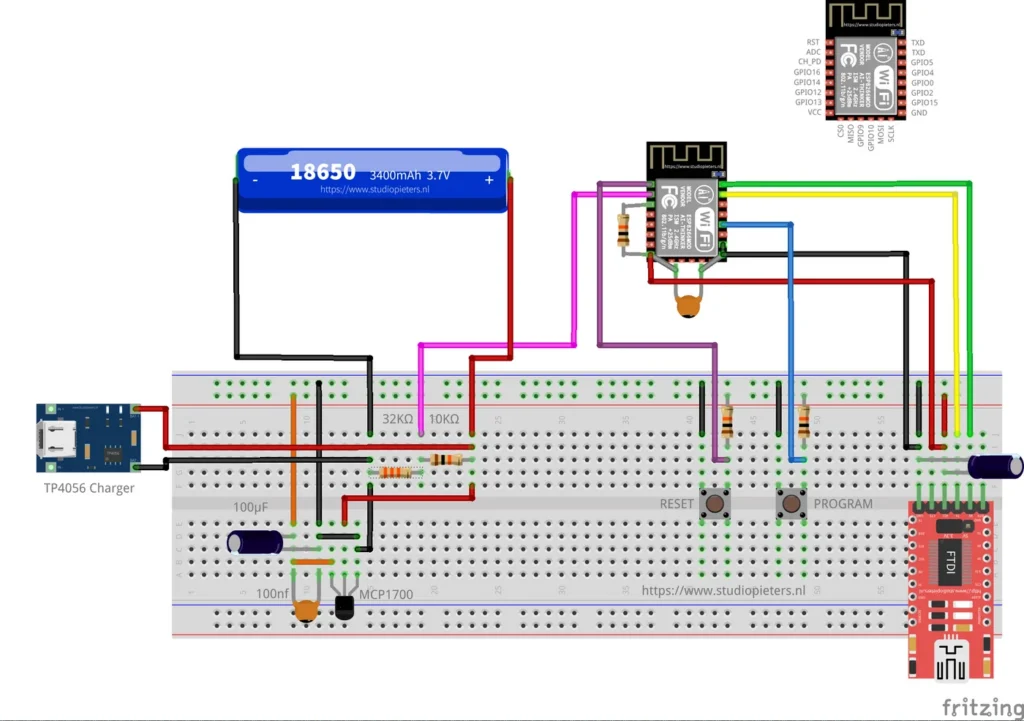
A proof of concept: an ESP8266 that measures an 18650 cell through a voltage divider and reports a low battery to Apple Home.
Read more
HomeKit
ESP8266 HomeKit Battery Status with an 18650 Cell
A proof of concept: an ESP8266 that measures an 18650 cell through a voltage divider and reports a low battery to Apple Home.
Read more
 HomeKit
ESP32 Power Plug
For years, the Dutch retailer Action has offered affordable smart-home devices under the brand LSC Smart Connect.
Read more
HomeKit
ESP32 Power Plug
For years, the Dutch retailer Action has offered affordable smart-home devices under the brand LSC Smart Connect.
Read more
More HomeKit
Keep building.
Switches, sensors, plugs and blinds: more accessories that you build yourself and add to the Home app.
All HomeKit