
Reference
DRV8825 Pinout
The pin reference for the DRV8825 stepper motor driver module: 16 pins, up to 1/32 microstepping, how to set the current limit and how to wire it without damaging the driver.
- Up to 2.2 A per coil
- Up to 1/32 microstepping
- 8.2 to 45 V motor supply
- 3.3 V and 5 V logic
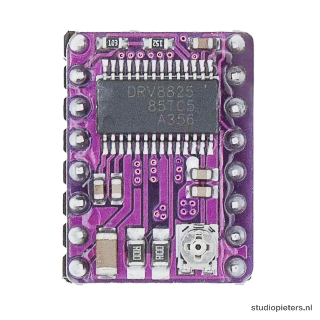
Overview
The DRV8825 is a stepper motor driver chip from Texas Instruments. It is used on 3D printers, CNC machines, camera sliders and robots, usually on a small breakout board like the one from Pololu. It is not a programmable board. A microcontroller sends it a STEP pulse for every step and a DIR level for the direction, and the DRV8825 switches the high currents in the motor coils.
No Wi-Fi, Bluetooth or Matter badge here on purpose: this module has no radio and no processor, it only drives a motor. Only badges for what this exact module supports are shown.
Chip and board
The chip is the DRV8825 from Texas Instruments. The board in this guide is the Pololu DRV8825 carrier (item 2133), which adds the current-limit trimpot, the two 0.100 Ω sense resistors, a 4-layer, 2 oz copper circuit board that draws heat out of the chip, and a 16-pin header. It runs from a motor supply of 8.2 to 45 V and needs no separate logic supply.
Many cheap modules copy this layout and silkscreen. Check the labels printed on your own board against the drawings below before you connect a motor, because the pin names and the position of the trimpot can differ on a clone.
In the drawings the chip is at the top and the trimpot at the bottom right. That is the Pololu board turned half a turn, so the pin names in this guide are the ones printed on the silkscreen, read in the drawing from top to bottom.
Getting started
The three steps below use any microcontroller that can make a pulse, for example an Arduino or an ESP32. Set the current limit before you connect a motor.
Hello World: turn a motor
This sketch turns the motor one full turn in each direction, using full steps. The pin numbers are examples, use the pins that you wired. A motor with 1.8 degrees per step needs 200 steps for one turn.
const int STEP_PIN = 2;
const int DIR_PIN  = 3;

void setup() {
  pinMode(STEP_PIN, OUTPUT);
  pinMode(DIR_PIN, OUTPUT);
}

void turn(int steps, bool forward) {
  digitalWrite(DIR_PIN, forward ? HIGH : LOW);
  for (int i = 0; i < steps; i++) {
    digitalWrite(STEP_PIN, HIGH);
    delayMicroseconds(800);
    digitalWrite(STEP_PIN, LOW);
    delayMicroseconds(800);
  }
}

void loop() {
  turn(200, true);
  delay(1000);
  turn(200, false);
  delay(1000);
}
The driver needs each STEP pulse, high and low, to last at least 1.9 µs. The 800 µs here is far slower and a safe start. This sketch is a minimal example, it was not run on a board for this guide.
Specifications
Values from the Pololu DRV8825 carrier page.
Driver
| Chip | DRV8825, microstepping driver for one bipolar stepper motor |
| Motor supply (VMOT) | 8.2 to 45 V |
| Maximum current | 2.5 A per coil for the chip. The sense resistors limit the module to 2.2 A per coil |
| Without extra cooling | About 1.5 A per coil. Above that you need a heat sink or forced air |
| Step sizes | Full, 1/2, 1/4, 1/8, 1/16 and 1/32 step |
| Current sense resistors | 0.100 Ω, current limit in amps = VREF x 2 |
| Decay mode | Mixed decay |
| Minimum STEP pulse | 1.9 µs high and 1.9 µs low |
Logic and protection
| Logic levels | Works directly with 3.3 V and 5 V systems, no logic supply needed |
| Protection | Over-current shutdown, over-temperature shutdown, under-voltage lockout, short-to-ground and shorted-load protection |
| Internal pull-downs | 100 kΩ on M0, M1, M2, STEP, DIR, RST and EN, 1 MΩ on SLP |
Physical
| Size | 0.6 x 0.8 inch (15.2 x 20.3 mm) |
| Pins | 16, in two rows of 8 at 2.54 mm pitch, header supplied (soldered or loose, depending on the version) |
| Board | 4-layer, 2 oz copper, exposed ground pad on the back |
Dimensions
The module is 0.6 by 0.8 inch, about 15.2 by 20.3 mm, with two rows of 8 pins at 2.54 mm pitch, so the 16 pins span 17.78 mm along the board. Pololu does not give the distance between the two rows, so measure your own board before you design a case or a PCB footprint.

Source: the size printed in Pololu’s dimension picture. The drawing is schematic: the chip and the trimpot are simple blocks.
Pinout diagram: component side
The component side has the chip and the trimpot. The motor pins are in the left column and the control pins in the right column. The two ground pins are not the same job: use the one next to VMOT for the motor supply and the one next to FLT for the ground of your microcontroller.

Pinout diagram: back
The back is mirrored: the same pins sit in the other column. It has the large exposed ground pad under the chip, which you can use to move heat away. The circled via is the test point for VREF, the voltage that sets the current limit.

Pins at a glance
All 16 pins grouped by job. Only STEP and DIR need to be driven all the time.

Pin reference
The same pins as a table, as printed on the board. The order is the one of the component-side drawing: the motor column from top to bottom, then the control column from top to bottom.
| Name | Function | Notes |
|---|---|---|
| GND | Ground, to the microcontroller | Next to FLT |
| FLT | Fault output | Goes low when over-current or over-temperature protection switches the outputs off. Safe to connect to a logic supply |
| A2, A1 | Motor coil A | The two wires of one coil |
| B1, B2 | Motor coil B | The two wires of the other coil |
| GND | Ground, motor supply | Next to VMOT |
| VMOT | Motor supply, 8.2 to 45 V | Add a capacitor of at least 47 µF close to the board |
| DIR | Direction | Pulled low by default |
| STEP | Step input | One pulse is one microstep, pulled low by default |
| SLP | Sleep | Must be high to run, pulled low by default |
| RST | Reset | Must be high to run, pulled low by default |
| M2, M1, M0 | Step size | See the table below. All low means full step |
| EN | Enable, active low | Pulled low by default, so the driver is on when you leave it open |
Setting the current limit
The current limit is the most important setting. The motor supply is usually much higher than the motor needs, so the driver limits the coil current actively. Set it at or below the current rating of your motor.
- Power the board without a motor connected.
- Measure the voltage at the VREF test point (the circled via on the back) against GND.
- Turn the trimpot until the voltage is the wanted current divided by 2.
The current limit in amps is VREF x 2, because the sense resistors are 0.100 Ω. For a motor rated at 1 A, set VREF to 0.5 V.
You can also put the driver in full-step mode and measure the current in one coil, without sending STEP pulses. The measured current is 0.7 times the limit, because both coils are on and each is limited to about 70% in full-step mode. Do not use the current at the power supply: it is not the coil current.
Microstepping
M0, M1 and M2 select the step size. They are pulled low internally, so leaving all three open gives full steps. The microstep modes only work well when the current limit is low enough that the current limiting is active, otherwise the motor can skip microsteps.
| M0 | M1 | M2 | Step size |
|---|---|---|---|
| Low | Low | Low | Full step |
| High | Low | Low | Half step |
| Low | High | Low | 1/4 step |
| High | High | Low | 1/8 step |
| Low | Low | High | 1/16 step |
| High | Low | High | 1/32 step |
| Low | High | High | 1/32 step |
| High | High | High | 1/32 step |
A motor with 1.8 degrees per step has 200 full steps per turn. In 1/4-step mode that is 800 microsteps per turn.
Enable, reset, sleep and fault
The chip has three inputs for its power state. RST and SLP are pulled low by default, and while either one is low the driver does nothing. Connect both to a logic high (2.2 to 5.25 V) or to an output of your microcontroller. EN is active low and pulled low by default, so the driver is enabled when you leave it open.
FLT is an output that goes low when the outputs are switched off by over-current protection or over-temperature shutdown. On the Pololu board a 10 kΩ resistor connects it to SLP, so it has a pull-up as long as SLP is held high, and a 1.5 kΩ resistor in series protects the pin.
DRV8825 compared with the A4988
The Pololu DRV8825 has the same size and almost the same pinout as the A4988 carrier, so it often works as a drop-in replacement. These are the differences that matter.
| DRV8825 | A4988 | |
|---|---|---|
| Maximum supply | 45 V | 35 V |
| Finest step size | 1/32 | 1/16 |
| Minimum STEP pulse | 1.9 µs | 1 µs |
| Current without extra cooling (Pololu full-step tests) | About 1.5 A per coil | 1.2 A per coil (Black Edition), 1 A (original) |
| Pin next to the SLP pin | FLT, a fault output | VDD, the logic supply |
| Motor pins | A1, A2, B1, B2 | 1A, 1B, 2A, 2B (same connections give the same motor behavior) |
The mode selection that gives 1/16 step on the A4988 gives 1/32 step on the DRV8825. The current limit trimpot is in a different place and the relation between VREF and the current is different, so set it again.
Real gotchas
- The motor does not move. RST and SLP are low by default. Connect both to a logic high first.
- Never connect or disconnect the motor while the driver is powered. It can destroy the driver. Switch off before you rewire anything.
- Voltage spikes can kill the board. It uses low-ESR ceramic capacitors, and a spike on long power leads can pass the 45 V rating even on a 12 V supply. Put an electrolytic capacitor of at least 47 µF across VMOT and GND, close to the board.
- Set the current before the first run. Both the driver and the motor can overheat on a limit that is too high.
- It gets hot. Above about 1.5 A per coil it needs a heat sink or forced air, and the module can burn you long before the chip overheats.
- Header pins on the wrong side. If you solder the pins with the silkscreen side up, the trimpot may not turn fully. Set the current limit before you solder them.
- A clone can differ. Compare the silkscreen of your board with the drawings above, and check the trimpot, before you connect a motor.
- Measure the coil, not the supply. The current at the power supply is lower than the coil current and says little about the limit.
What to build with it
- A 3D printer or a CNC machine, one driver per axis
- A motorized camera slider or a pan and tilt head
- A robot with accurate wheel or arm movement
- Any machine that must move an exact distance without a position sensor
Drive it with an Arduino Nano or an ESP32, whichever you have.
Safety notes
Before you wire anything up
- Never connect or disconnect the motor while the driver is powered. The resulting spike can destroy it.
- Set the current limit (VREF) before you run the motor. A limit that is too high can overheat the driver and the motor.
- Use a motor supply of 8.2 to 45 V and a capacitor of at least 47 µF across VMOT and GND.
- Cool the module if you run more than about 1.5 A per coil, and do not touch it while it works.
- STEP and DIR are logic inputs that work with 3.3 V and 5 V. Connect RST and SLP to a logic high of 2.2 to 5.25 V, not to the motor supply.
Conclusion
The DRV8825 drives a bipolar stepper motor from just a STEP and a DIR pin, with step sizes down to 1/32. Set the current limit with VREF x 2 before you connect a motor, hold RST and SLP high, put a capacitor of at least 47 µF across the motor supply and never rewire it while it is powered.
Sources: the Pololu DRV8825 stepper motor driver carrier page and its minimal wiring diagram, and the silkscreen photo of the board.
Related
 Guide
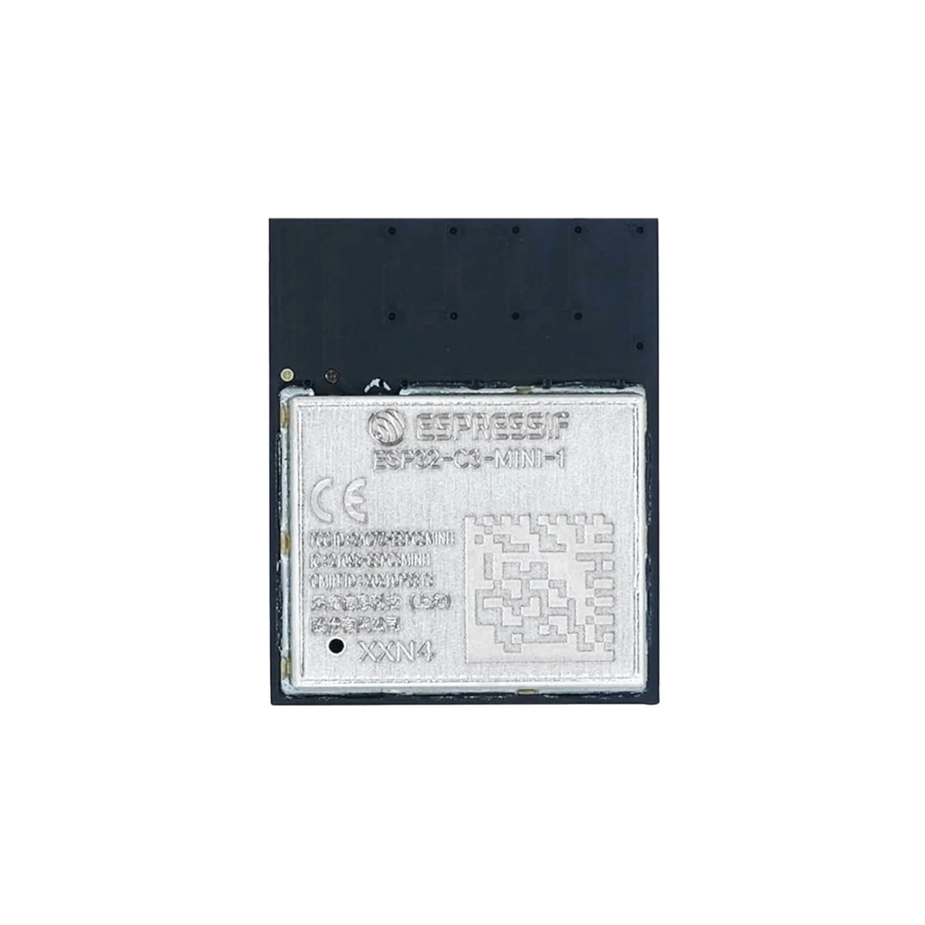
ESP32-C3-MINI-1 Pinout
The complete pin reference for the ESP32-C3-MINI-1 module: a single RISC-V core, Wi-Fi and Bluetooth LE, and the exact pins you can safely reuse.
Read more
 Reference
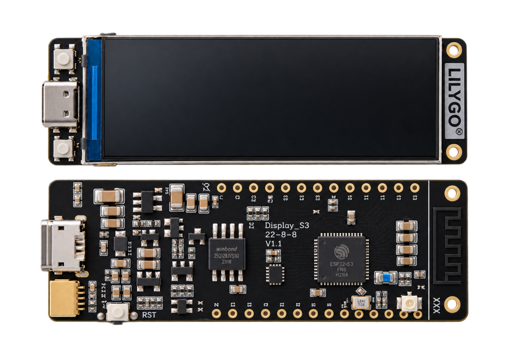
LILYGO T-Display-S3 Pinout
The LILYGO T-Display-S3 pin reference: the 8-bit display bus, the GPIO15 power pin, battery, buttons, programming settings and the traps.
Read more
 Reference
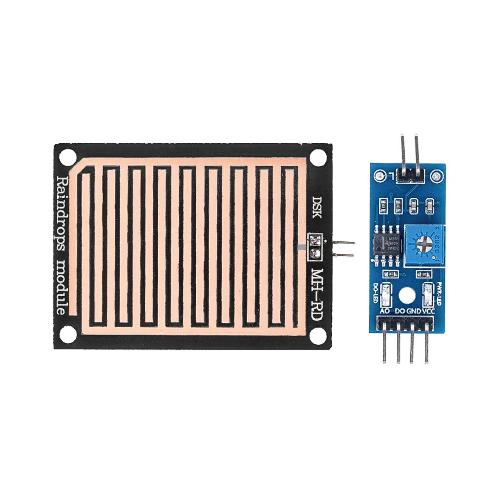
MH-RD Raindrop Detection Module
A low-cost rain sensor built from two boards: a copper-trace sensor plate and an LM393 comparator breakout. Covers the pinout, how the analog/digital outputs behave when the plate gets wet, and wiring it to an ESP32 or Arduino.
Read more
More guides
Keep building.
From ESP32 HomeKit accessories to Arduino and ATtiny reference guides, there’s more where this came from.
All guides