
Guide
ESP8266 Pinout
The complete pin reference for the ESP8266 on NodeMCU and Wemos D1 Mini style boards: 9 usable GPIOs, one analog input, and the exact pins you can safely reuse.
- ESP8266
- NodeMCU
- Safety notes
- 3 min read
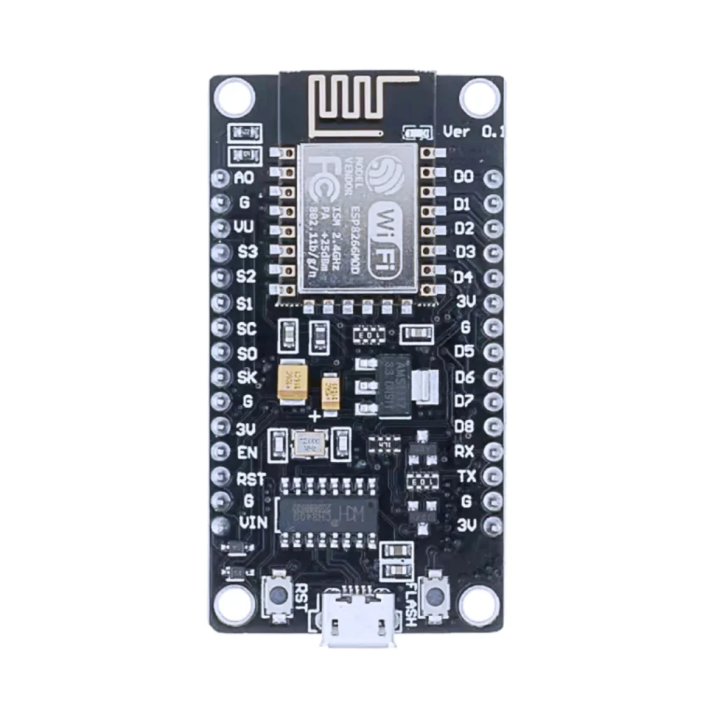
Overview
This guide covers the ESP8266 as it appears on NodeMCU and Wemos D1 Mini style development boards, the way almost everyone actually encounters this chip. The bare chip and its ESP-12E/F module have far more pins internally, but these boards only break out the ones listed below, add USB, voltage regulation, and reset/flash buttons for easy prototyping.

No Bluetooth badge here on purpose: the ESP8266 has no Bluetooth radio at all, Wi-Fi is the only wireless feature on this chip.
Getting started
Most ESP8266 dev boards use a CH340 or CP2102 USB-to-serial chip, install its driver first if your board doesn’t show up as a serial port.
Hello World: blink an LED
The microcontroller equivalent of “Hello World”: GPIO2 (D4) toggles once a second. Most NodeMCU and Wemos D1 Mini boards already have an onboard LED here, wired active-low, so LOW turns it on.
#define LED_PIN 2 // D4, onboard LED on most boards, active low
void setup() {
  pinMode(LED_PIN, OUTPUT);
}

void loop() {
  digitalWrite(LED_PIN, LOW);  // on  delay(1000);
  digitalWrite(LED_PIN, HIGH); // off  delay(1000);
}
Select your exact board first, see “Getting started” above. There’s no ESP-IDF example here, ESP-IDF targets the newer ESP32 family, not the ESP8266.
Specifications
Official specifications for the ESP8266 chip.
Compute
| Chip | ESP8266 |
| Module | ESP-12E / ESP-12F |
| CPU | Single-core Tensilica L106, 80 or 160 MHz |
| Flash | 4 MB typical (board-dependent) |
Radio
| Wi-Fi | 802.11 b/g/n, 2.4 GHz |
| Bluetooth | None |
Physical
| Operating voltage | 3.3V |
| GPIOs | 9 usable on most dev boards |
| ADC | 1 channel, 10-bit |
Pinout diagram
The ESP8266 module’s full pin matrix, including the alternate SPI/JTAG/UART functions not broken out on most dev boards.

GPIO quick reference
Board labels (D0–D8) are what’s silkscreened on NodeMCU/Wemos boards, they don’t match the underlying GPIO numbers.
| Board label | Chip pin | Special function | Boot state |
|---|---|---|---|
| D0 | GPIO16 | Deep sleep wake-up (separate RTC domain, no PWM/I2C/SPI) | Free |
| D1 | GPIO5 | I2C SCL (common default) | Free |
| D2 | GPIO4 | I2C SDA (common default) | Free |
| D3 | GPIO0 | Boot mode select | Strapping, must be HIGH |
| D4 | GPIO2 | Onboard LED on many boards (active low) | Strapping, must be HIGH |
| D5 | GPIO14 | SPI CLK (common default) | Free |
| D6 | GPIO12 | SPI MISO (common default) | Free |
| D7 | GPIO13 | SPI MOSI (common default) | Free |
| D8 | GPIO15 | SPI CS (common default) | Strapping, must be LOW |
| RX | GPIO3 | UART0 RX | Free |
| TX | GPIO1 | UART0 TX | Free |
| A0 | ADC0 | Analog input, 0–1V range only | Free |
Flashing pins (UART0)
Used by a USB-to-serial adapter (or the onboard one) to upload firmware.
| Function | Pin | Description |
|---|---|---|
| TXD0 | GPIO1 | ESP8266 → PC (output) |
| RXD0 | GPIO3 | PC → ESP8266 (input) |
| EN / CH_PD | EN | Chip enable (active HIGH) |
| GPIO0 | GPIO0 | Pull LOW to enter flash mode |
| RST | RST | Pull LOW to reset |
Safety notes
Before you wire anything up
- D3/GPIO0 and D4/GPIO2 must read HIGH at boot, D8/GPIO15 must read LOW, an accidental pull-down or pull-up on these can stop the board from booting.
- A0 tolerates 0–1V only on the bare chip, most dev boards add a divider for 0–3.3V, check your specific board before assuming either.
- This chip runs at 3.3V logic, a 5V signal on any pin can damage it.
Related
 Reference
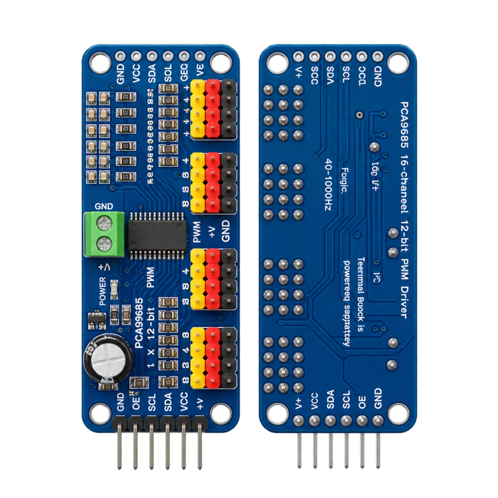
PCA9685 16-Channel PWM/Servo Driver
A 16-channel, 12-bit I2C PWM driver that turns two ESP32 wires into enough hardware-generated outputs for a whole rack of servos or an LED array. Covers the pinout, address selection, register map, and the safe way to power servos without browning out the board.
Read more
 Reference
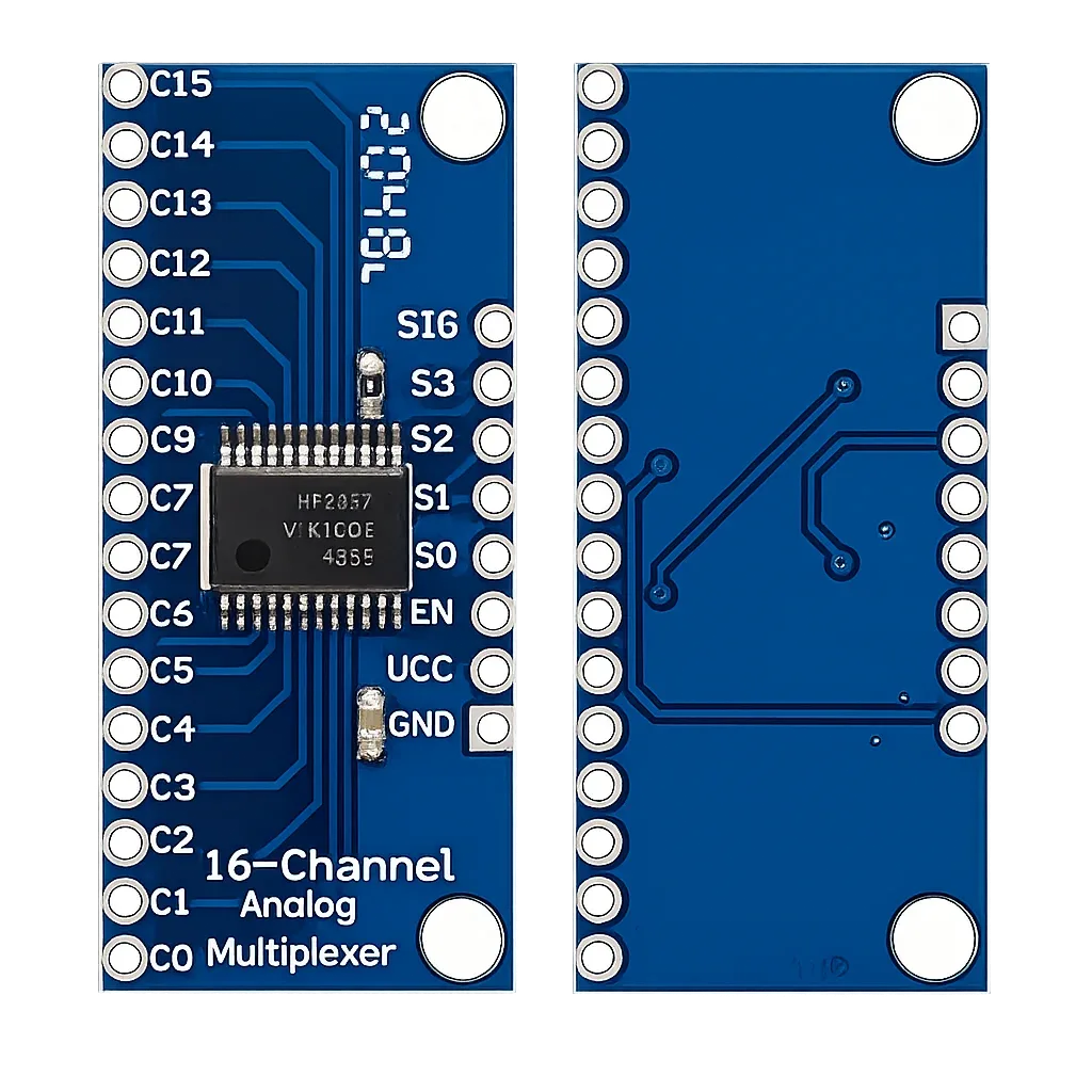
CD74HC4067 16-Channel Analog Multiplexer – Complete Guide
A 16-position analog switch controlled by just 4 GPIO pins, turning one ADC input into sixteen. This guide covers the pinout, channel-select truth table, ESP32 wiring, ESP-IDF/Arduino code, and how it compares to the 74HC4051 and the ADS1115.
Read more
 Guide
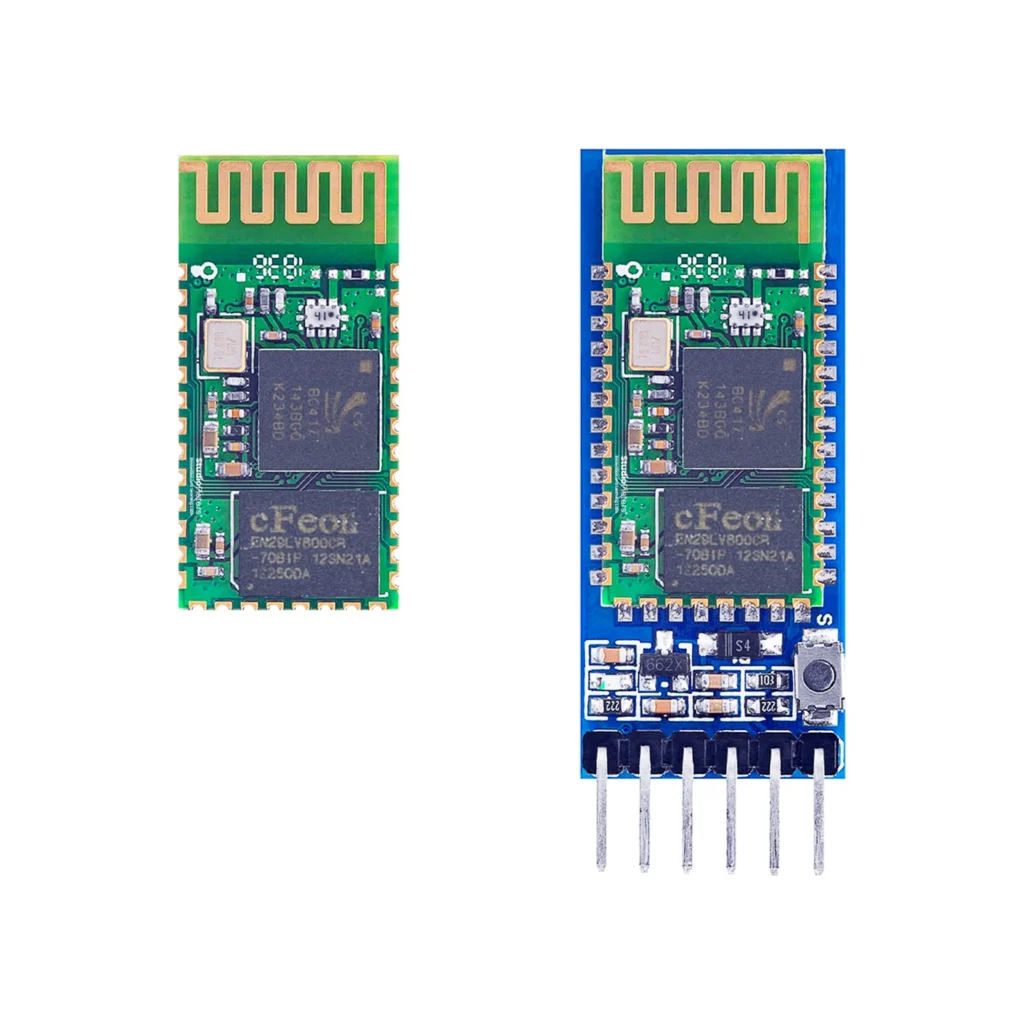
HC-05 Bluetooth Module Pinout
The complete pin reference for the HC-05: a UART-to-Bluetooth bridge available as a bare 34-pin module or a simple 6-pin breakout board.
Read more
More guides
Keep building.
From ESP32 HomeKit accessories to Arduino and ATtiny reference guides, there’s more where this came from.
All guides