
Reference
STM32F103C8T6 “Blue Pill” Pinout
This site's first STMicroelectronics board and first chip with no wireless radio at all: an Arm Cortex-M3 on a breadboard-friendly board with a decade-long tutorial and library ecosystem, and two well-known clone-batch quirks worth knowing before you plug one in.

The “Blue Pill” is a cheap, breadboard-friendly development board built around STMicroelectronics’ STM32F103C8T6, an Arm Cortex-M3 microcontroller. Unlike every other board on this site so far, it has no Wi-Fi or Bluetooth radio built in at all, it’s a pure microcontroller board, add an external radio module if a project needs wireless. Its huge, decade-old hobbyist ecosystem (mainly through the community-maintained STM32duino Arduino core) is why it’s still one of the most-used STM32 boards for learning Arm Cortex-M development.
Chip and board
The STM32F103C8T6 is a 72MHz Arm Cortex-M3 with 64KB of flash and 20KB of RAM, in a 48-pin LQFP package. The Blue Pill board breaks it out onto a 23×53mm PCB with two 20-pin headers (breadboard-compatible spacing), a micro-USB connector, a reset button, and two boot-mode jumpers.
| Spec | Value |
|---|---|
| Core | Arm Cortex-M3, 72MHz |
| Flash / RAM | 64KB / 20KB |
| Logic voltage | 3.3V (most GPIOs are 5V-tolerant, marked “FT” in ST’s own datasheet, but check per-pin before assuming) |
| USB | USB 2.0 full-speed device (micro-USB) |
| Wireless | None built in |
| Package | LQFP48 |
Pin headers
Real pin labels as printed on the board’s own silkscreen (source: stm32-base.org’s Blue Pill reference).
| Header | Pins |
|---|---|
| Left header | VBAT, PC13, PC14, PC15, PA0–PA7, PB0, PB1, PB10, PB11, NRST, 3.3V, GND |
| Right header | 3.3V, GND, 5V, PB9, PB8, PB7, PB6, PB5, PB4, PB3, PA15, PA12, PA11, PA10, PA9, PA8, PB15, PB14, PB13, PB12 |
| SWD header (4-pin) | 3.3V, PA13 (SWDIO), PA14 (SWCLK), GND |
| USB connector | 5V, PA11 (D−), PA12 (D+), GND |
PA0–PA7 and PB0/PB1 double as a 12-bit ADC. Most pins also carry a timer channel (TIM1–TIM4) for hardware PWM, check ST’s own STM32F103C8T6 datasheet for the exact alternate-function map before a design that depends on a specific pin’s timer.
Real gotchas
- The onboard USB D+ pull-up resistor is wrong on many clone batches. USB device detection needs a 1.5kΩ pull-up on PA12 (D+), but many Blue Pill clones ship with a 10kΩ or 4.7kΩ resistor there instead (commonly labeled R10 on the silkscreen), which stops a PC from ever recognizing the board over USB. Measure resistance between PA12 and the 3.3V pad with a multimeter; if it’s nowhere near 1.5kΩ, the fix is replacing R10 (or adding a second 1.5k–1.8kΩ resistor in parallel with it). This is a genuine, widely-documented hardware defect, not a software problem, don’t spend hours debugging drivers before checking this.
- PC13 (the onboard LED) has weak output drive. It shares internal circuitry with the RTC oscillator, so it can only reliably sink a small current, fine for the onboard LED, not for driving anything else directly. It’s also wired active-low (sinks current to turn the LED on), a blink sketch that drives it HIGH-for-on will appear inverted.
- The 5V header pin connects straight to USB VBUS, with no protection. Don’t power the board from both USB and an external 5V source into that pin at the same time.
Boot modes and flashing
Two jumpers (labeled BOOT0 and BOOT1) select where the chip starts executing on reset or power-up:
| BOOT0 | BOOT1 | Boots from |
|---|---|---|
| 0 | x | Main flash (normal run mode) |
| 1 | 0 | System memory (built-in USART bootloader) |
| 1 | 1 | Embedded SRAM |
Three real ways to get code onto it:
- ST-Link (recommended): a cheap ST-Link V2 clone plugged into the 4-pin SWD header (PA13/PA14), works with both BOOT jumpers left at 0, no jumper changes needed between flashing and running.
- USB-to-serial + BOOT0 jumper: a USB-to-TTL adapter into PA9 (TX)/PA10 (RX), BOOT0 set to 1 before flashing (triggers the built-in USART bootloader), then back to 0 to run normally.
- Direct USB (advanced): possible once a USB-capable bootloader is flashed onto the chip by one of the two methods above, but only works if the USB pull-up resistor is correct in the first place, see the gotcha above first.
Programming
The most beginner-friendly path is the community-maintained STM32duino “STM32 MCU based boards” package in the Arduino IDE’s Boards Manager, it gives Arduino-style pinMode()/digitalWrite() functions using the same PA/PB/PC pin names printed on the board. STMicroelectronics’ own official tooling, STM32CubeIDE with the HAL/LL libraries, is the alternative for lower-level register access or when a project outgrows the Arduino abstraction, not covered here in code form since it’s a different, larger toolchain.
void setup() {
  pinMode(PC13, OUTPUT);
}

void loop() {
  digitalWrite(PC13, LOW);   // LED on (active-low)
  delay(500);
  digitalWrite(PC13, HIGH);  // LED off
  delay(500);
}
Conclusion
The Blue Pill is a cheap way into real Arm Cortex-M development, with the tradeoff of no built-in wireless (unlike this site’s ESP32 and nRF52840 boards) and two well-known clone-batch defects worth checking before assuming a dead board. Need Wi-Fi or Bluetooth in the same design? Pair it with a separate radio module, or reach for an ESP32 or nRF52840 board instead if the whole project can live on one chip.
Related
 Guide
ESP8685-WROOM-03 Pinout
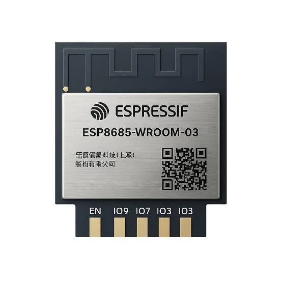
The complete pin reference for the ESP8685-WROOM-03 module: Espressif’s enhanced ESP32-C2-family chip in an 11-pin package, and the exact pins you can safely reuse.
Read more
Guide
ESP8685-WROOM-03 Pinout
The complete pin reference for the ESP8685-WROOM-03 module: Espressif’s enhanced ESP32-C2-family chip in an 11-pin package, and the exact pins you can safely reuse.
Read more
 Reference
The Complete Guide to the HC-SR501 PIR Motion Sensor
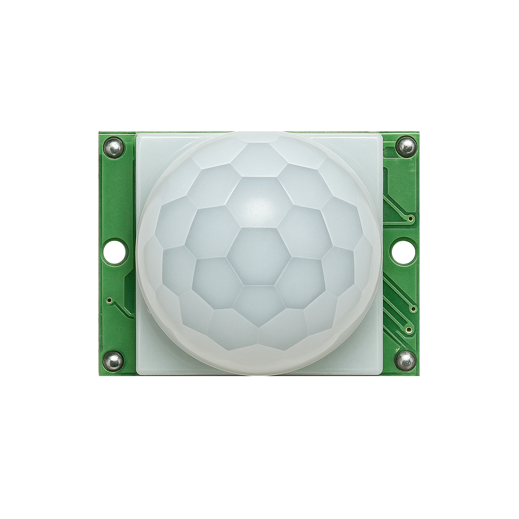
One of the cheapest ways to add motion detection to a project: a passive infrared sensor with adjustable delay and sensitivity, a simple digital HIGH/LOW output, and both retriggerable and non-retriggerable modes.
Read more
Reference
The Complete Guide to the HC-SR501 PIR Motion Sensor
One of the cheapest ways to add motion detection to a project: a passive infrared sensor with adjustable delay and sensitivity, a simple digital HIGH/LOW output, and both retriggerable and non-retriggerable modes.
Read more
 Reference
SHT40 / SHT41 Temperature and Humidity Sensor Complete Guide
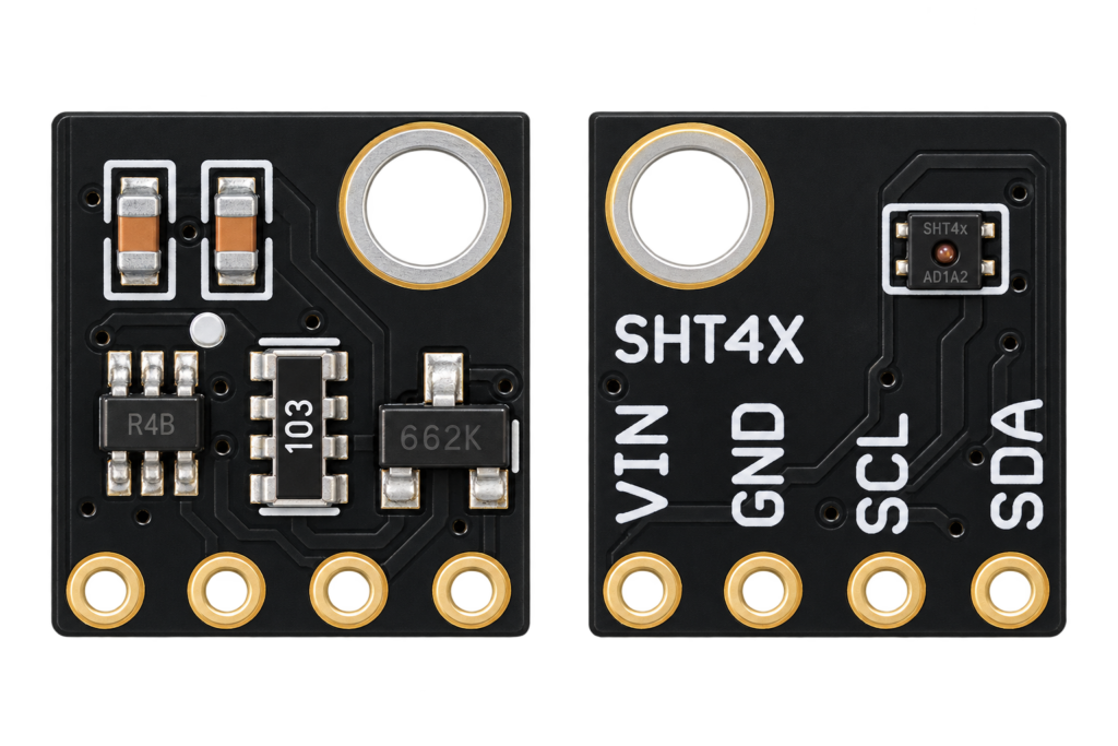
Sensirion's fourth-generation SHT4x sensors trade the SHT3x series' heater-based self-test for an ultra-low idle power budget and a slightly tighter accuracy spec. This guide covers wiring an SHT40 or SHT41 to an ESP32, real I2C addressing, and which SHT generation actually makes sense for a new project.
Read more
Reference
SHT40 / SHT41 Temperature and Humidity Sensor Complete Guide
Sensirion's fourth-generation SHT4x sensors trade the SHT3x series' heater-based self-test for an ultra-low idle power budget and a slightly tighter accuracy spec. This guide covers wiring an SHT40 or SHT41 to an ESP32, real I2C addressing, and which SHT generation actually makes sense for a new project.
Read more
More guides
Keep building.
From ESP32 HomeKit accessories to Arduino and ATtiny reference guides, there’s more where this came from.
All guides