
Reference
Guide to the HWFS-1 Anemometer
A passive, cup-style wind speed sensor with a built-in voltage generator, no external power needed. This guide covers the analog output, wiring to an ESP32 ADC pin, and the calibration formula to convert voltage into km/h or m/s.
- Analog 0 to 2 V
- Passive
- no supply
- Up to 200 km/h
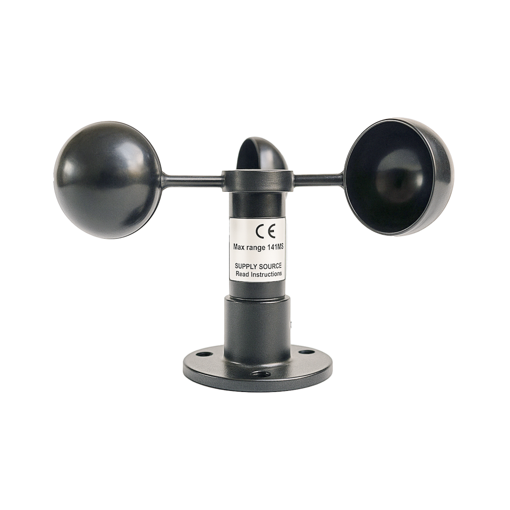
Measuring wind speed is essential for weather stations, agricultural monitoring, HVAC automation, and safety systems. The HWFS-1 Anemometer is a cost-effective, analog-output wind speed sensor, ideal for both DIY and industrial environments. In this guide, you’ll learn everything about the voltage-type HWFS-1, its principle, wiring, and how to use it effectively with microcontrollers.
What is the HWFS-1 Anemometer?
The HWFS-1 is a mechanical cup-style wind speed sensor with an integrated voltage generator. As the wind rotates the 3-cup rotor, the internal generator produces a voltage signal proportional to wind speed, no external power supply is required.
The details in this guide come from the common documentation of the HWFS-1 anemometer. I did not read a datasheet for this update, and units from different sellers vary.
Key Features
- Model: HWFS-1
- Type: Analog cup-type anemometer
- Output: Voltage (0–2V typical, max 4V)
- Power: Passive (no external power needed)
- Wiring: 2 wires (Signal + Ground)
- Material: ABS plastic, weather-resistant
- Max Wind Speed: 200 KM/h
- Recommended Range: < 100 KM/h
- Installation: Bolt-through base, 3 × 6mm holes at 120°
Dimensions
The HWFS-1 is a three-cup anemometer with an ABS body. It mounts with a bolt-through base with three 6 mm holes at 120°. The cup diameter, the height and the cable length vary between sellers, so measure yours before you design a mast or a bracket. Mount it horizontally and in open air.
Source: the details come from the existing text of this guide and common practice, not from a datasheet read for this update.
How It Works
When wind blows, the cups rotate and an internal electromagnetic generator produces a voltage. The output voltage increases linearly with wind speed:
- 0V → no wind
- 2V → ~100 KM/h
- 4V (max) → ~200 KM/h (not recommended for continuous use)
HWFS-1 Wiring
| Wire | Function |
|---|---|
| Black | GND (Ground) |
| Black with Stripe | Signal (Voltage out, 0–2V typical) |
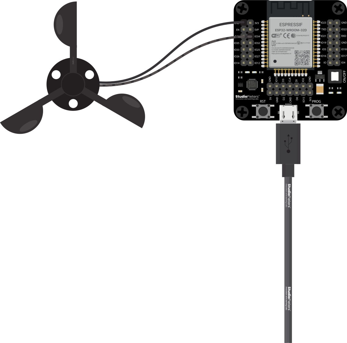
Connect the signal wire to an ADC (Analog-to-Digital Converter) pin on your microcontroller (e.g., ESP32, Arduino) and the black wire to GND.
There is no polarity, but consistency is best practice.
Example Wiring (ESP32)
| HWFS-1 Wire | ESP32 Pin |
|---|---|
| Black with stripe | GPIO 34 (ADC) |
| Solid black | GND |
Sample Arduino Code (Analog Reading)
#define WIND_SENSOR_PIN 34

void setup() {
  Serial.begin(115200);
}

void loop() {
  int analogValue = analogRead(WIND_SENSOR_PIN); // 0–4095 on ESP32
  float voltage = analogValue * 3.3 / 4095.0;     // Convert to volts
  float windSpeedMS = voltage * 14.0;             // Wind speed in m/s
  float windSpeedKMH = voltage * 50.0;            // Wind speed in km/h

  Serial.print("Wind Speed: ");
  Serial.print(windSpeedMS);
  Serial.print(" m/s | ");
  Serial.print(windSpeedKMH);
  Serial.println(" km/h");

  delay(1000);
}
Calibration Formula
You can estimate wind speed directly using these formulas:
- Wind speed (km/h) = Voltage (V) × 50
- Wind speed (m/s) = Voltage (V) × 14
Example: if the voltage is 0.5V, then wind speed ≈ 25 km/h ≈ 7 m/s.
Practical Applications
- Weather Stations: Monitor outdoor wind conditions
- HVAC Automation: Adjust systems based on outside airflow
- Agriculture: Control irrigation and ventilation based on wind
- Wind-Triggered Systems: LED beacons, safety alerts, etc.
Best Practices
- Mount horizontally at an open, unobstructed location
- Avoid metallic interference or lightning-prone spots
- Use waterproof enclosures for electronics
- Shield analog cable if longer than 3 meters
- Use a stable analog reference voltage for accuracy
Real gotchas
- The output can exceed the ADC range. The sensor outputs 0 to 2 V typically and up to 4 V at its maximum, while an ESP32 ADC reads at most 3.3 V and is not linear near the top. Use a voltage divider so the signal stays below the ADC limit, set the 11 dB attenuation, and calibrate.
- The ESP32 ADC is not linear. Calibrate against a reference anemometer, or use
analogReadMilliVolts(). - The 14 and 50 factors are nominal. They assume 2 V for 100 km/h. Check them with a known wind speed.
- The sensor has a start-up wind speed. Very low wind does not turn the cups, so there is a dead zone near zero.
- Long cables pick up noise. Shield the cable beyond 3 metres, and keep it away from mains wires.
- No polarity, but be consistent. Use the same wire as ground every time.
- Lightning. A metal mast outdoors attracts lightning. Ground it properly and keep the electronics protected.
- Ice and dust. They change the friction of the bearing and the reading.
Safety notes
Before you wire anything up
- Mount the anemometer on a stable mast. A falling mast can hurt someone.
- Lightning can follow a mast to your electronics. Ground the mast and add surge protection.
- Keep the supply of the electronics at 3.3 V on the analog pin.
- Never connect the board to mains voltage. Keep it on a low-voltage supply.
- Disconnect the power before you change the wiring.
Conclusion: Wind Speed Made Simple
The voltage-type HWFS-1 Anemometer is a reliable, easy-to-use analog wind speed sensor ideal for embedded systems. Its passive design requires no power supply, and it integrates seamlessly with ADC-enabled microcontrollers like the ESP32 and Arduino. With linear voltage output and simple formulas, it’s a perfect sensor for anyone needing real-time wind data.
Related
 Reference
The Ultimate Guide to the SHT Sensor Series
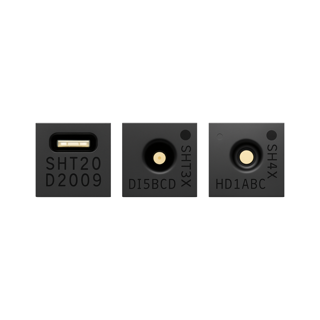
Sensirion's SHT2x/3x/4x family are factory-calibrated I2C temperature and humidity sensors with low drift and fast response. This guide compares the three series, covers wiring an SHT31 to an ESP32, and helps pick the right model for accuracy, power budget or outdoor use.
Read more
 Reference
HX711 + Load Cell Weight Sensor Complete Guide
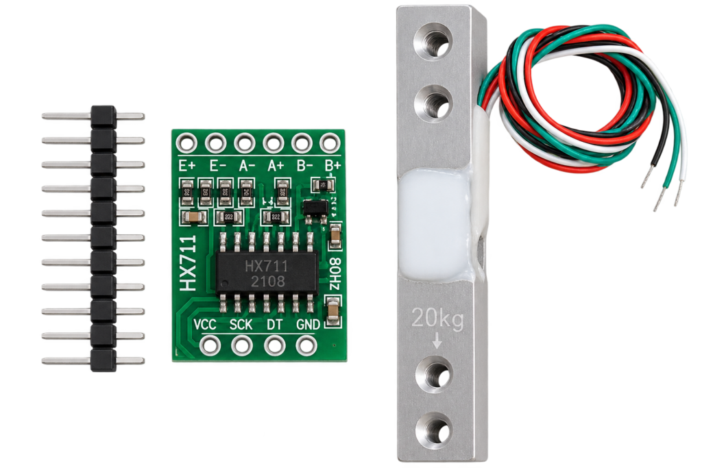
The HX711 24-bit load cell amplifier: datasheet specifications, pins, load cell wiring, the serial protocol, calibration, code and the traps that give a drifting weight.
Read more
More guides
Keep building.
From ESP32 HomeKit accessories to Arduino and ATtiny reference guides, there’s more where this came from.
All guides