
Electronics
0.91-inch OLED Display on an ATtiny85
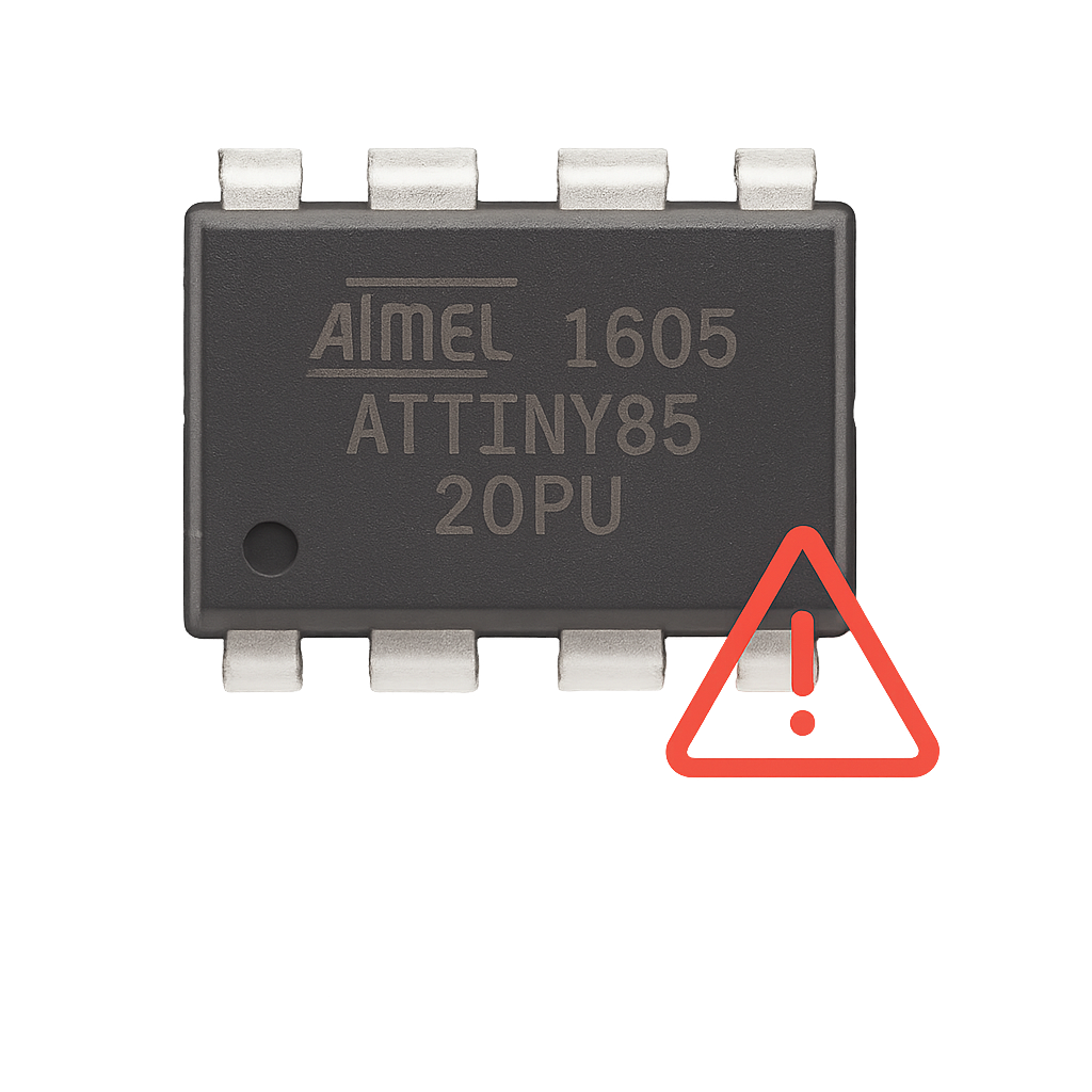
The ATtiny85 is a compact and low-power microcontroller ideal for minimalist electronics.
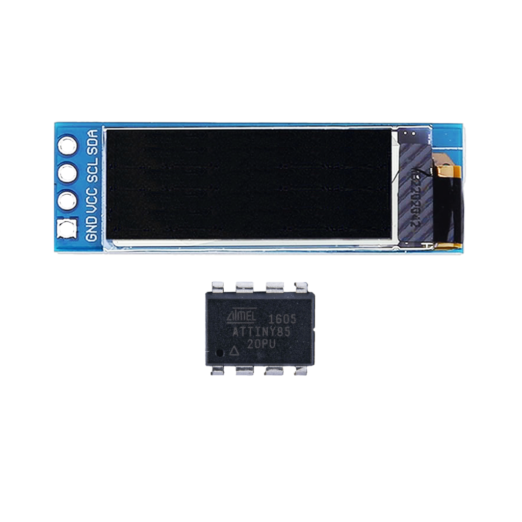
The ATtiny85 is a compact and low-power microcontroller ideal for minimalist electronics. Whether you’re building a wearable, a sensor node, or a creative display, the ATtiny85 paired with a 0.91” OLED display delivers powerful functionality in an ultra-tiny footprint. In this guide, you’ll learn how to flash the ATtiny85, wire it up to an OLED display, and power it from a CR2032 battery.
What is the ATtiny85?
Minimalist MCU:
The ATtiny85 is an 8-bit microcontroller from Atmel (now Microchip) with 8KB flash, 512B SRAM, and 6 GPIO pins. It’s programmable via Arduino and ideal for low-power, space-constrained projects.
Features:
- 8-bit AVR RISC architecture
- Up to 20MHz clock speed (internal oscillator)
- 5 I/O pins (plus reset)
- I2C, SPI (via USI), ADC, PWM support
- Extremely low power consumption
- DIP-8 or SMD form factor
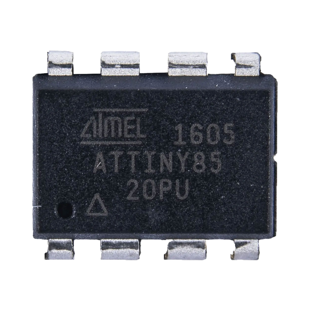
Flashing the ATTiny85 using an Arduino
Before connecting the OLED, the ATTiny85 must be programmed. You can do this using an Arduino Uno as an ISP (In-System Programmer).
Hardware Needed
- Arduino Uno
- ATtiny85 (DIP-8)
- Breadboard + jumper wires
- 10µF capacitor
- Arduino IDE installed
Steps
- Setup Arduino as ISP:
- Open the Arduino IDE.
- Load File > Examples > 11.ArduinoISP > ArduinoISP.
- Upload to your Arduino Uno.
- Connect the ATtiny85:
| Arduino Uno | ATtiny85 |
|---|---|
| Pin 10 | RESET |
| Pin 11 | MOSI (PB0) |
| Pin 12 | MISO (PB1) |
| Pin 13 | SCK (PB2) |
| 5V | VCC |
| GND | GND |
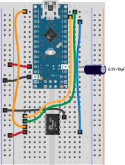
Note: Don’t forget to place a 10µF capacitor between RESET and GND on the Uno to disable auto-reset.
- Install ATtiny Board Support:
- Arduino IDE → Preferences → Additional Board URLs:
https://raw.githubusercontent.com/damellis/attiny/ide-1.6.x-boards-manager/package_damellis_attiny_index.json - Boards Manager → Install ATtiny by David A. Mellis.
- Arduino IDE → Preferences → Additional Board URLs:
- Board Settings:
- Tools → Board: “ATtiny25/45/85”
- Processor: “ATtiny85”
- Clock: “8 MHz (internal)”
- Programmer: “Arduino as ISP”
- Burn Bootloader:
Tools → Burn Bootloader - Upload Sketches:
Use Upload using Programmer (Shift + Upload icon)
Connecting the OLED Display (128×32, I2C)
This display uses the SSD1306 driver and communicates via I2C. It’s a perfect fit for ATtiny85 thanks to its small size and low power usage.
Display Specs
- Resolution: 128×32 pixels
- Interface: I2C
- Operating voltage: 3.3V–5V
- Pins: VCC, GND, SCL, SDA
ATtiny85 Pinout
| Pin | Function |
|---|---|
| 1 (PB5) | Reset (or GPIO) |
| 2 (PB3) | GPIO3 / ADC3 |
| 3 (PB4) | GPIO4 / ADC2 / SCL |
| 4 | GND |
| 5 (PB0) | GPIO0 / MOSI / SDA |
| 6 (PB1) | GPIO1 / MISO |
| 7 (PB2) | GPIO2 / SCK |
| 8 | VCC |
I2C Connection
| OLED Display | ATtiny85 |
|---|---|
| VCC | VCC (Pin 8) |
| GND | GND (Pin 4) |
| SCL | PB2 (Pin 7) |
| SDA | PB0 (Pin 5) |
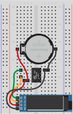
Note: I2C on ATtiny85 uses Software I2C (bit-banged). Libraries like TinyWireMAdafruit_SSD1306 + TinyWireM support this.
Powering with a CR2032 Battery
To make the project portable, we’ll power it using a 3V CR2032 coin cell.
Power Tips
- Connect CR2032 + to VCC, to GND
- Use a low-dropout voltage regulator if running peripherals at 3.3V with stable output
- Keep code optimized to minimize power draw
- Use
sleepmodes to extend battery life
Required Libraries (Arduino IDE)
#include <TinyWireM.h>#include <Tiny4kOLED.h>Install these via the Library Manager or GitHub.TinyWireMTiny4kOLED ondersteunt de SSD1306 128×32 displays.
Display Example: StudioPieters Project (Centered Text)
#include <TinyWireM.h>#include <Tiny4kOLED.h>void setup() { TinyWireM.begin(); // Initialize I2C oled.begin(); // Initialize OLED display oled.clear(); // Clear the screen oled.setFont(FONT8X16); // Use 8x16 font oled.on(); // Turn on the display // Line 1 (Y = 1) oled.setCursorCentered(1); oled.print(F("StudioPieters")); // Line 2 (Y = 2) oled.setCursorCentered(2); oled.print(F("ATTiny85 - OLED (I2C")); // Line 3 (Y = 3) oled.setCursorCentered(3); oled.print(F("Project"));}void loop() { // Static display, no refresh needed}ATtiny85 OLED Quick Reference
| Function | Pin | Notes |
|---|---|---|
| SDA | PB0 (5) | Use TinyWireM |
| SCL | PB2 (7) | Use TinyWireM |
| Power VCC | Pin 8 | 2.7V–5.5V (3V ideal) |
| Power GND | Pin 4 | Connect to ground |
| Display driver | SSD1306 | Compatible with Tiny4kOLED |
| I2C library | TinyWireM | Bit-banged implementation |
Best Practices and Common Mistakes
- Don’t use hardware
Wire.h, useTinyWireMfor I2C on ATtiny. - Keep OLED update rate low to conserve battery.
- Pull-up resistors on SDA/SCL are usually not needed (OLED module includes them).
- Don’t exceed CR2032 max current draw (~20mA continuous).
- Use
sleep_mode()inloop()to save power. - Mind ATtiny85 memory limitations (only 8KB flash).
Conclusion: Tiny MCU, Big Possibilities
The ATtiny85 + OLED combo is a powerful foundation for compact, battery-powered display projects. Whether you’re creating a branding badge, a sensor output monitor, or a creative wearable, this minimalist design packs a surprising punch.
Mastering the connection between the ATtiny85 and OLED unlocks a new tier of low-power, display-driven innovation, perfect for the maker who believes less is more.
Happy Building!
Related
 Electronics
Arduino Nano HV Rescue Shield
If you’ve ever configured the fuse bits of an ATtiny incorrectly, for example disabling the RESET pin or choosing the wrong clock source, regular ISP programming will fail. Your microcontroller will appear to be bricked.
Read more
Electronics
Arduino Nano HV Rescue Shield
If you’ve ever configured the fuse bits of an ATtiny incorrectly, for example disabling the RESET pin or choosing the wrong clock source, regular ISP programming will fail. Your microcontroller will appear to be bricked.
Read more
 3D printing
Nest Protect Ceiling Mounting Ring
Sometimes the biggest challenges come from the smallest details. The Nest Protect (2nd Generation) is a beautiful piece of hardware, a combined smoke and CO alarm, that comes in two versions: battery powered and 220V wired.
Read more
Opinion
The ESP32 Family, Explained Honestly
A plain-language walkthrough of every real ESP32 family (and the ESP8266), what each is actually good at, and which one to reach for depending on what you're building.
Read more
3D printing
Nest Protect Ceiling Mounting Ring
Sometimes the biggest challenges come from the smallest details. The Nest Protect (2nd Generation) is a beautiful piece of hardware, a combined smoke and CO alarm, that comes in two versions: battery powered and 220V wired.
Read more
Opinion
The ESP32 Family, Explained Honestly
A plain-language walkthrough of every real ESP32 family (and the ESP8266), what each is actually good at, and which one to reach for depending on what you're building.
Read more