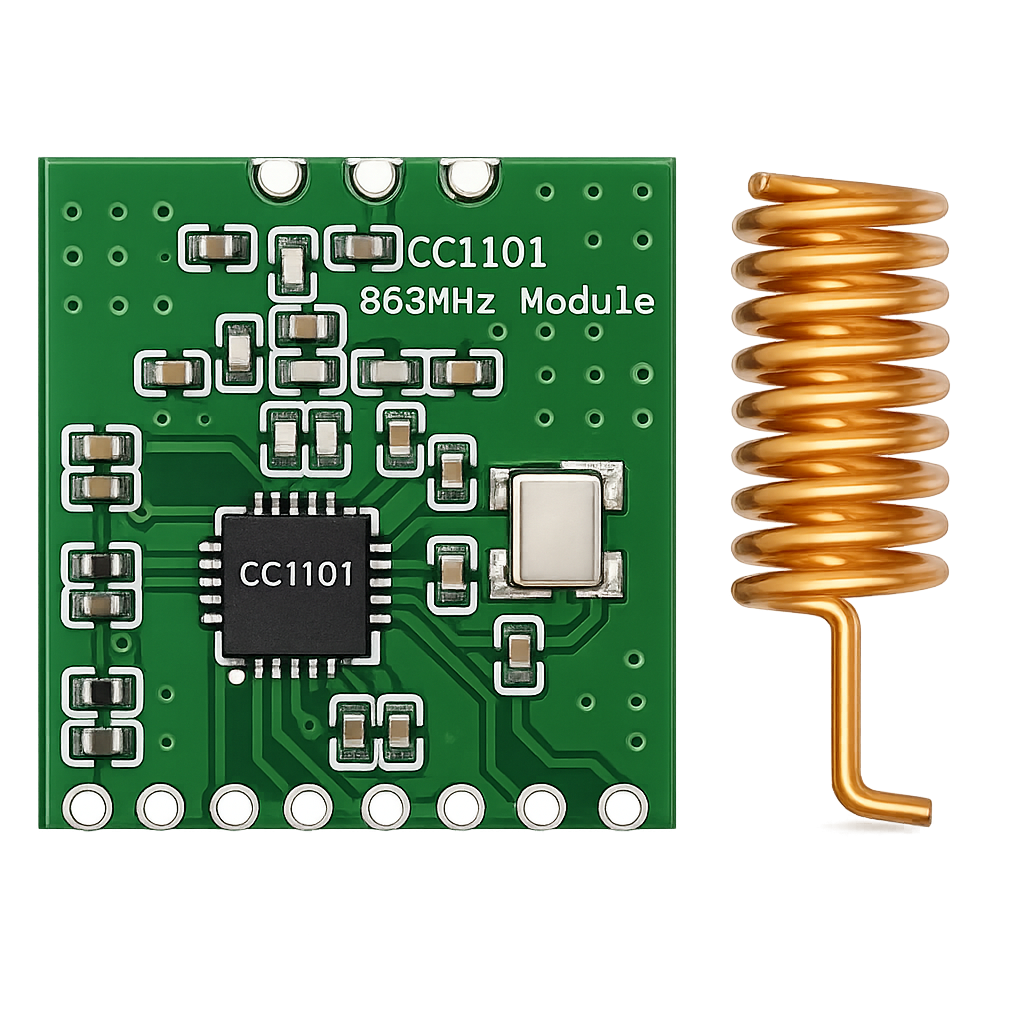
The CC1101 868MHz SPI RF module is a compact, low-power sub-GHz transceiver widely used in IoT, industrial telemetry, home automation and custom RF networks. The module is based on the CC1101 from Texas Instruments and offers significantly more flexibility than simple ASK/OOK transmitter modules.
In this complete guide we cover:
- What the CC1101 is
- Technical specifications
- Pinout
- ESP32 wiring
- ESP-IDF SPI setup
- Register configuration explained
- TX/RX workflow
- RSSI handling
- EU 868 MHz regulations
- CC1101 vs SX1276 (LoRa) comparison
- Practical engineering tips
What is the CC1101?
The CC1101 is a programmable sub-GHz RF transceiver designed for low-power wireless communication in ISM bands:
- 315 MHz
- 433 MHz
- 868 MHz (Europe)
- 915 MHz (US)
Unlike basic RF modules, the CC1101 includes:
- Hardware packet handling
- CRC generation/checking
- Address filtering
- RSSI measurement
- Configurable modulation
- TX and RX FIFO buffers
It is a true RF transceiver — not just a transmitter or receiver.
Technical Specifications
| Parameter | Value |
|---|---|
| Frequency range | 387–464 MHz / 779–928 MHz |
| Common EU version | 868 MHz |
| Interface | SPI |
| Modulation | 2-FSK, GFSK, MSK, OOK |
| Data rate | 0.6 – 600 kbps |
| Output power | up to +12 dBm |
| RX sensitivity | approx. -110 dBm |
| RX current | ~14 mA |
| TX current | 16–30 mA |
| Sleep mode | < 1 µA |
| Supply voltage | 3.3V only |
⚠️ The CC1101 is not 5V tolerant.
Pinout
Most breakout boards expose the following pins:
| Pin | Description |
|---|---|
| VCC | 3.3V supply |
| GND | Ground |
| SCK | SPI clock |
| MISO | SPI MISO |
| MOSI | SPI MOSI |
| CSN | Chip select |
| GDO0 | Configurable interrupt pin |
| GDO2 | Configurable interrupt pin |

The GDO pins can signal:
- Packet sent
- Packet received
- Carrier detect
- FIFO thresholds
These are essential for interrupt-driven designs.
Connecting to an ESP32
Typical wiring using the VSPI bus:
| CC1101 | ESP32 |
|---|---|
| VCC | 3V3 |
| GND | GND |
| SCK | GPIO18 |
| MISO | GPIO19 |
| MOSI | GPIO23 |
| CSN | GPIO5 |
| GDO0 | GPIO4 |
This configuration works well with ESP-IDF default SPI setup.
SPI Initialization (ESP-IDF)
Minimal SPI configuration:
spi_bus_config_t buscfg = {
    .miso_io_num = 19,
    .mosi_io_num = 23,
    .sclk_io_num = 18,
    .quadwp_io_num = -1,
    .quadhd_io_num = -1
};spi_device_interface_config_t devcfg = {
    .clock_speed_hz = 1000000,
    .mode = 0,
    .spics_io_num = 5,
    .queue_size = 3,
};spi_bus_initialize(VSPI_HOST, &buscfg, SPI_DMA_CH_AUTO);
spi_bus_add_device(VSPI_HOST, &devcfg, &cc1101_handle);
The CC1101 supports higher SPI speeds (up to 10 MHz), but 1 MHz is stable during development.
Register Configuration Explained
The CC1101 is fully controlled through configuration registers.
Frequency Registers
- FREQ2
- FREQ1
- FREQ0
Typical values for 868 MHz:
FREQ2 = 0x21
FREQ1 = 0x65
FREQ0 = 0x6A
These values define the RF carrier frequency using the internal frequency synthesizer.
Modulation Configuration
Registers:
- MDMCFG4
- MDMCFG3
- MDMCFG2
These control:
- Data rate
- Channel bandwidth
- Modulation format
- Sync word handling
Example configuration for:
- 38.4 kbps
- 2-FSK
- CRC enabled
Packet Configuration
Registers:
- PKTCTRL1
- PKTCTRL0
- PKTLEN
Typical setup:
PKTCTRL0 = 0x05 // Variable length + CRC enabled
The CC1101 automatically handles:
- Preamble
- Sync word
- CRC
- Packet length
This significantly reduces firmware complexity.
Transmit (TX) Flow
Basic transmit sequence:
- Set device to IDLE
- Flush TX FIFO
- Write packet length
- Write payload
- Send STX strobe
- Wait for GDO0 interrupt
Example:
cc1101_strobe(SIDLE);
cc1101_strobe(SFTX);cc1101_write_reg(TXFIFO, length);
cc1101_write_burst(TXFIFO, payload, length);cc1101_strobe(STX);
Using GDO0 as “packet sent” interrupt makes this efficient and non-blocking.
Receive (RX) Flow
- Send SRX strobe
- Wait for GDO0 interrupt
- Read packet length
- Read payload
- Check CRC status
cc1101_strobe(SRX);// Wait for interruptcc1101_read_reg(RXFIFO, &length);
cc1101_read_burst(RXFIFO, buffer, length);
Interrupt-driven RX avoids polling and improves power efficiency.
RSSI Measurement
The RSSI register provides signal strength information.
Formula:
RSSI_dBm = (RSSI_dec / 2) - RSSI_offset
Typical RSSI offset ≈ 74.
This allows:
- Link quality estimation
- Channel scanning
- Adaptive TX power
- Smart retry mechanisms
EU 868 MHz Regulations
In Europe, the 868 MHz band is regulated with duty cycle limitations:
- 1% duty cycle
- 0.1% in certain sub-bands
This means: If you transmit for 1 second, you must remain silent for 99 seconds (in a 1% band). Always verify local regulations before deployment.
CC1101 vs SX1276 (LoRa)
A common alternative is the SX1276 from Semtech.
Comparison
| Feature | CC1101 | SX1276 |
|---|---|---|
| Modulation | FSK, GFSK, OOK | LoRa + FSK |
| Max Range | ~1 km | 5–15 km |
| Sensitivity | ~ -110 dBm | Down to -148 dBm |
| Data Rate | Up to 600 kbps | Very low (LoRa mode) |
| Latency | Low | High |
| Deterministic timing | Yes | No (LoRa spreading) |
When to Choose CC1101
- Low latency required
- Higher throughput needed
- Custom RF protocol
- Deterministic timing
- Industrial applications
When to Choose SX1276 (LoRa)
- Extreme range
- Battery-powered long-distance sensors
- Rural telemetry
- Very low data rate acceptable
Practical Engineering Tips
1. Antenna Is Critical
Quarter-wave antenna for 868 MHz:
≈ 8.6 cm
A poorly tuned antenna reduces range dramatically.

2. Lower Data Rate = Longer Range
Reducing bitrate improves receiver sensitivity.
3. Use Interrupts
Always use GDO0 for:
- TX complete
- RX received
Polling wastes CPU cycles and power.
4. Shielding & Layout
- Keep antenna away from ground planes
- Keep SPI lines short
- Decouple VCC properly
RF layout matters.
Conclusion
The CC1101 868MHz SPI RF module remains one of the most versatile sub-GHz solutions for embedded firmware developers.
It offers:
- Low power consumption
- Good range
- High flexibility
- Full protocol control
- Deterministic timing
For ESP32 + ESP-IDF developers building custom RF stacks, the CC1101 is still an excellent engineering choice. If you want full control without the complexity of LoRaWAN, the CC1101 gives you exactly that.