
HomeKit
ESP8266 HomeKit Window Contact Sensor with a Hall Sensor
A HomeKit window contact sensor: an A3144 Hall sensor, a magnet, an ESP8266 and a 3D-printed housing that sticks to the frame. A test setup with the circuit explained from the datasheet.
- ESP8266
- HomeKit
- 4 min read
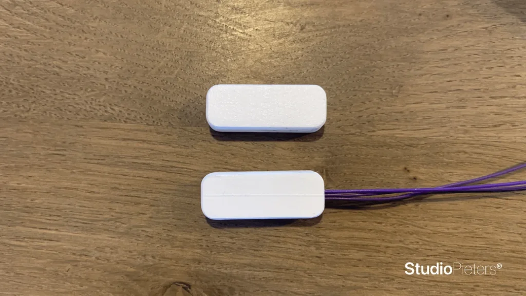
A wireless window contact sensor for Apple HomeKit. A small Hall-effect sensor notices a magnet, an ESP8266 reports it to the Home app, and the whole sensor sits in a 3D-printed housing that sticks to the window frame with double-sided tape.
The same build exists in four versions for four uses: this one for a window, and one each for a general contact sensor, a door and blinds. The housing shown here is a design of the author, and the model is not published anywhere. This is a test setup.
The four versions
| Version | Use |
|---|---|
| Window Contact Sensor | A window that is open or closed |
| Door Contact Sensor | A door that is open or closed |
| Blinds Contact Sensor | Blinds that are open or closed |
| Contact Sensor | Any other contact, such as a cupboard |
The hardware is the same, and the versions differ in the application. In the Home app you choose how the sensor is displayed: as blinds, a contact sensor, a door, a garage door or a window. An older version with a reed contact is the ESP8266 HomeKit Reed Contact Sensor.
The Hall sensor
The sensor is an A3144, a unipolar Hall-effect switch. From its datasheet: it runs on 4.5 to 24 V and has an open-collector output that can sink up to 25 mA. The output, on pin 3, switches low when the magnetic field at the sensor rises above its operate point, and goes high again when the field falls below the release point. The difference between the two points, the hysteresis, keeps it from flickering. In the datasheet, pin 1 is the supply and pin 2 is ground. The schematic below is drawn with its own pin numbers, so go by the labels VCC, GND and VOUT.
So the sensor needs no moving parts: put a magnet on the moving part, the sensor on the fixed part, and the output tells you whether they are close together.
The circuit
The A3144 is powered from 5 V, but the ESP8266 input takes 3.3 V. The circuit deals with that with two resistors on the output: R1, 10 kΩ, to +5 V, and R2, 20 kΩ, to ground.
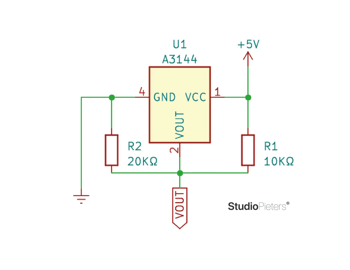
With no magnet near, the output is released, and the two resistors form a divider: 5 V times 20 kΩ divided by 30 kΩ is about 3.3 V, safe for the ESP8266. With a magnet near, the sensor pulls the output to ground. R1 also works as the pull-up that an open-collector output needs.
Hardware and wiring
| Component | Notes |
|---|---|
| NodeMCU (ESP8266) board | A development board with USB. See the ESP8266 pinout |
| A3144 Hall sensor | Supply, ground and output |
| Resistors | 10 kΩ and 20 kΩ, as in the circuit |
| Magnet | On the moving part of the window |
| 5 V USB power | The board is powered over USB |
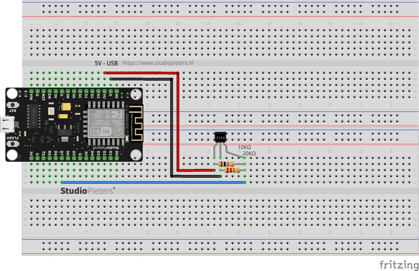
In the diagram, the sensor output goes to pin D7 of the NodeMCU, which is GPIO13. The pin is read from the diagram, since the repository holds no source code, so check it before you build.
The 3D-printed housing
The sensor and the magnet each get a small housing, and the sensor housing holds the electronics. The author printed a test version first, with the sensor inside.
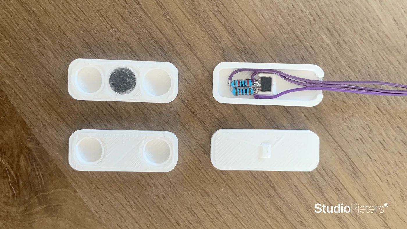
The housing is fixed with double-sided tape, and the gap between the two parts should be about 2 mm when the window is closed.
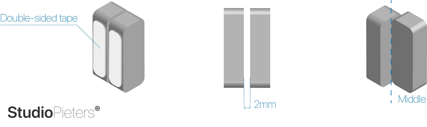
The model of the housing is a design of the author and is not published, so there is no download.
Flash and install
The installation is the same as for the other ESP8266 HomeKit accessories on this site. The firmware runs on ESP-Open-RTOS with Life Cycle Manager 2, which sets up the WiFi and installs updates over the air. The full steps, from installing esptool to flashing, joining the LCM- WiFi network and pairing, are in ESP8266 HomeKit Blinds.
In the portal, use these values:
| Field | Value |
|---|---|
| OTA repository | AchimPieters/ESP8266-HomeKit-Window-Contact-Sensor |
| OTA binary file | main.bin |
The portal also has a setting for the LED pin. For a high output, use the active-high option, “If active on 1”.
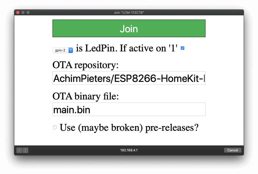
When the installation is done, scan the QR code the device generates in the Home app to add it.
In the Home app
The sensor first shows up as a plain sensor. After adding it, the Home app asks how to display it: as blinds, a contact sensor, a door, a garage door or a window. That choice decides the icon and the words the Home app uses.
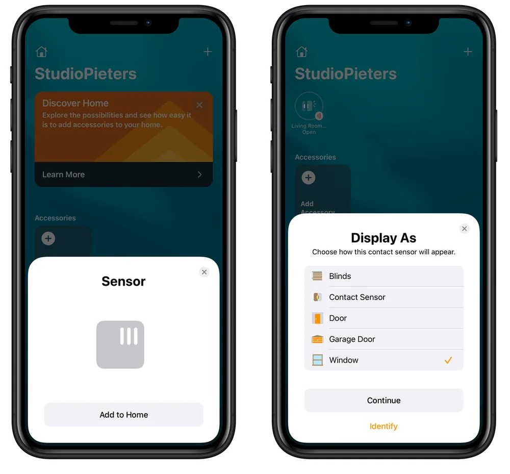
The screenshots show the Home app with an English interface.
Firmware releases
| Version | Date |
|---|---|
| 0.0.3 | 26 April 2021 |
| 0.0.2 | 26 April 2021 |
| 0.0.1 | 24 April 2021 |
Each release has a main.bin and a signature file, main.bin.sig.
Good to know
- This is a test setup and not a finished product.
- The HomeKit Accessory Protocol specification the firmware follows is the non-commercial version, for accessories you build yourself and do not distribute or sell.
- The repository is under the MIT licence and holds the firmware release, not the source code.
Everything is in the ESP8266-HomeKit-Window-Contact-Sensor repository on GitHub.
Related
 HomeKit
ESP8266 HomeKit Temperature and Humidity Sensor
A DHT11 or DHT22 with an ESP8266 as a temperature and humidity sensor in Apple Home, with a firmware version for each sensor and pin.
Read more
HomeKit
ESP8266 HomeKit Temperature and Humidity Sensor
A DHT11 or DHT22 with an ESP8266 as a temperature and humidity sensor in Apple Home, with a firmware version for each sensor and pin.
Read more
 HomeKit
ESP32 WiFi Bootstrap: Wi-Fi Provisioning with HomeKit Integration
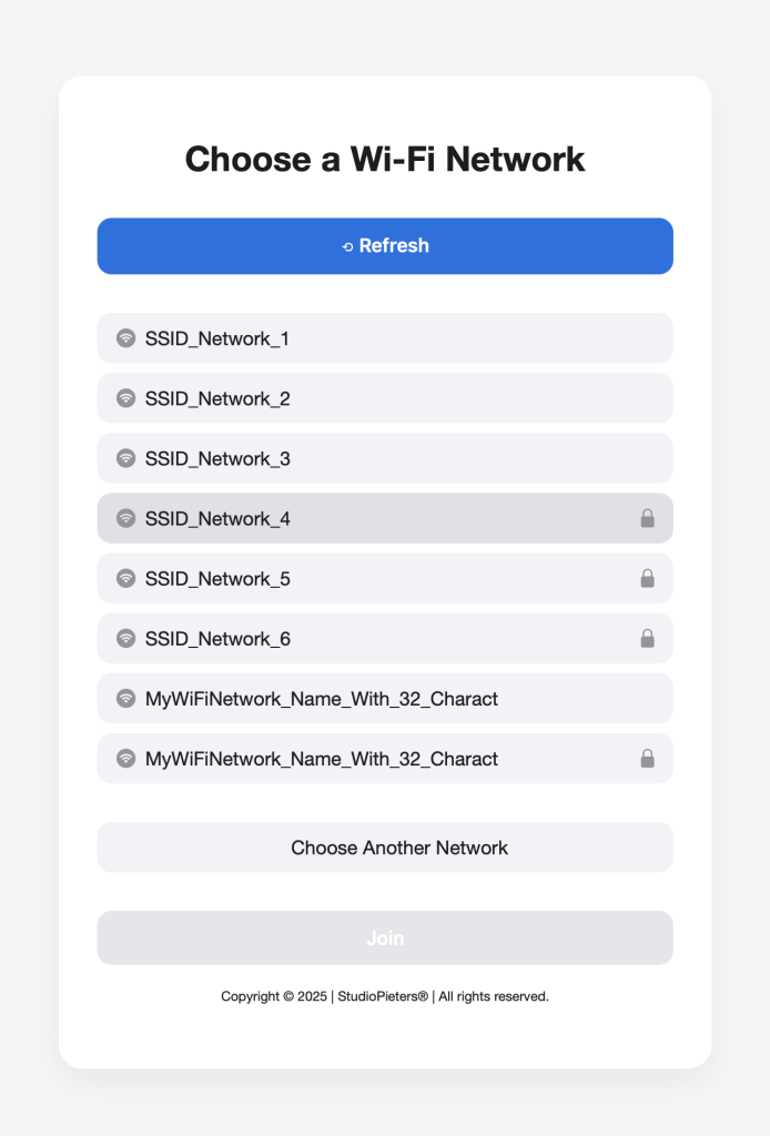
A lightweight Wi-Fi provisioning component for the ESP32: a captive portal for onboarding, credentials persisted in NVS, and a SoftAP fallback, paired here with the HomeKit LED example to show the full provisioning-to-pairing flow.
Read more
HomeKit
ESP32 WiFi Bootstrap: Wi-Fi Provisioning with HomeKit Integration
A lightweight Wi-Fi provisioning component for the ESP32: a captive portal for onboarding, credentials persisted in NVS, and a SoftAP fallback, paired here with the HomeKit LED example to show the full provisioning-to-pairing flow.
Read more
 HomeKit
ESP8266 HomeKit Switch as a Switch, Lamp or Fan
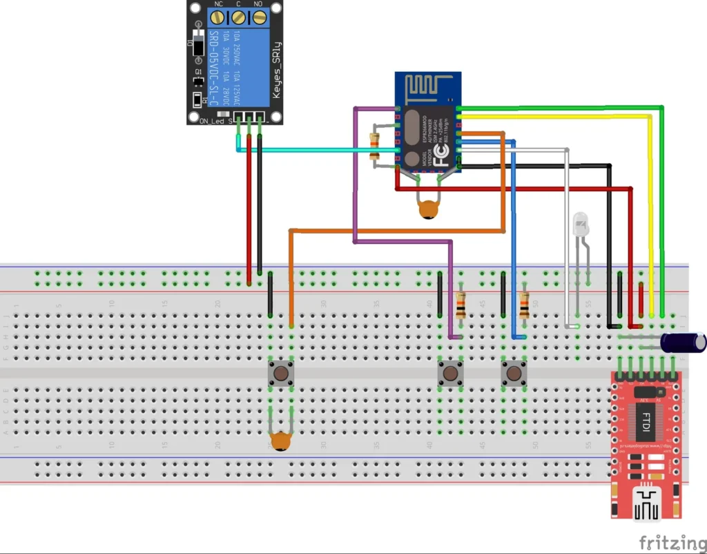
One ESP8266 relay firmware that Apple Home can show as a switch, a lamp or a fan, with a button on the board.
Read more
HomeKit
ESP8266 HomeKit Switch as a Switch, Lamp or Fan
One ESP8266 relay firmware that Apple Home can show as a switch, a lamp or a fan, with a button on the board.
Read more
More HomeKit
Keep building.
Switches, sensors, plugs and blinds: more accessories that you build yourself and add to the Home app.
All HomeKit