
CNC
Mini CNC Laser Engraver: A Build That Did Not Work
A small laser engraver with a 3D printed frame, two stepper motors, an Arduino Nano with GRBL and a 200 mW laser, and why it never engraved.
- Arduino
- CNC
- Archived
- Safety notes
Archived project
The GitHub repository for this project is archived: it is read-only and no longer updated. The project did not work in the end, which happens, and it was a case of trial and error. What follows describes the build as it was.
Laser safety
A laser like the one in this project can damage an eye permanently in a fraction of a second, also from a reflection. Never look into the beam, and never point it at a reflective surface. Wear laser safety glasses that are rated for the wavelength of your laser, and check the rating: the glasses used here were advertised for 190 to 1200 nm by the seller, which is not proof that they protect. Look for glasses with an EN 207 or EN 208 marking and the right protection level for a 650 nm laser. Work in a closed space, away from flammable material, and never leave the machine alone.
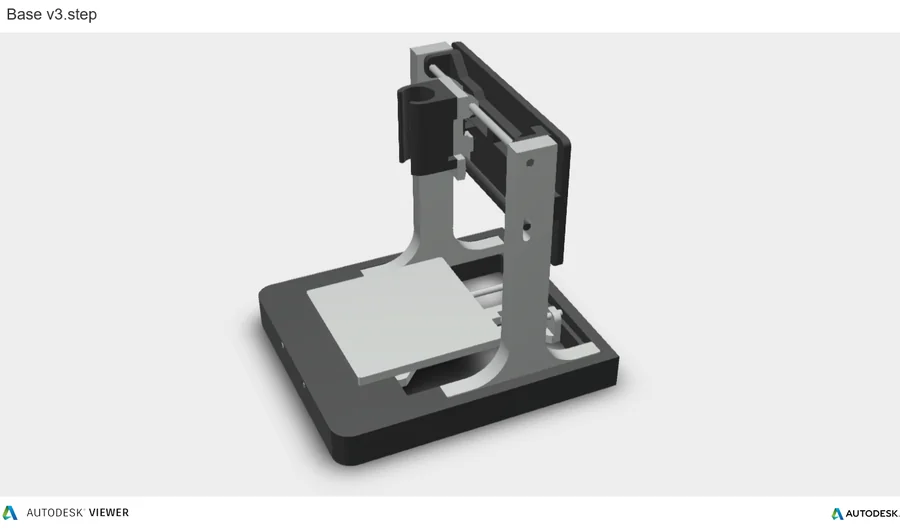
A small CNC laser engraver, built from 3D printed parts, two small stepper motors that were lying around, an Arduino Nano with GRBL and a red laser module. The idea was to burn a picture into wood from a G-code file.
It did not get there. The laser was not strong enough and the machine only left a few small burn marks on wood. This article shows how it was built and what came out of it, since a failed build still teaches a lot.
The laser
| Part | Details |
|---|---|
| Laser module | A focusable red dot laser module, 200 to 250 mW, 650 nm |
| Safety glasses | Laser safety glasses, advertised for 190 to 1200 nm |
This laser turned out not to be strong enough to engrave wood.
The 3D printed frame
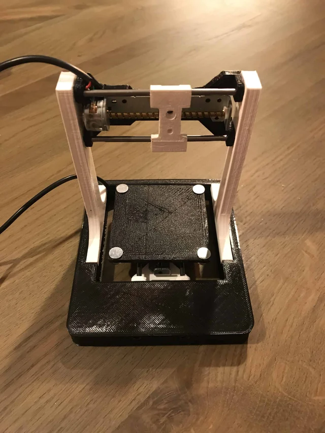
The frame is printed in parts, and the STL files are in the repository:
| File | Part |
|---|---|
| Base.stl | The base plate |
| Frame_Side_L_R.stl | The left and right sides of the frame |
| Rail_Frame.stl | The frame for the rails |
| X_Plate.stl | The plate for the X axis |
| Slider.stl | The slider that moves along the rails |
| Thread_Guide.stl | The guide for the threaded rod |
| Laser+Holder.stl | The holder for the laser module |
| Cable+Guide.stl | The guide for the cables |
| Back+Plate.stl | The back plate |
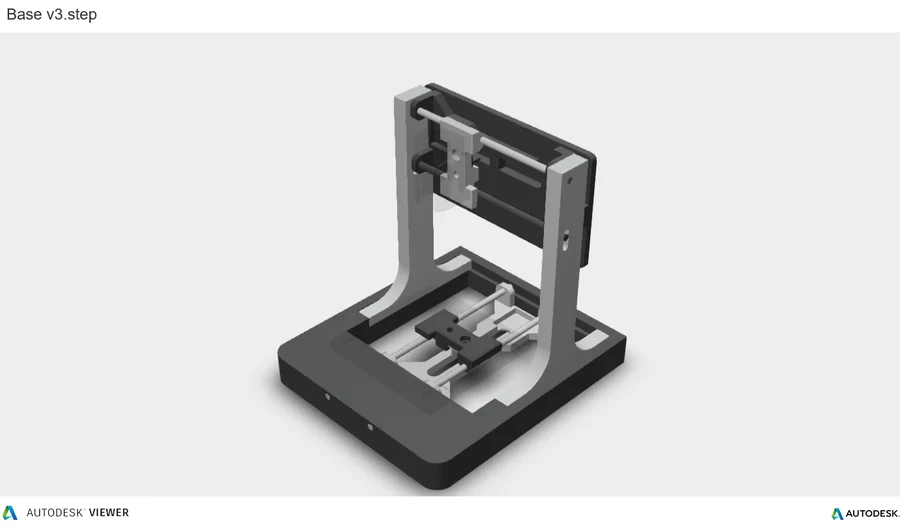
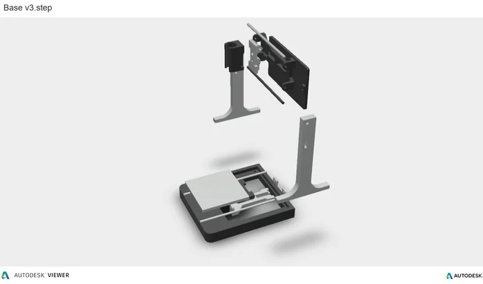
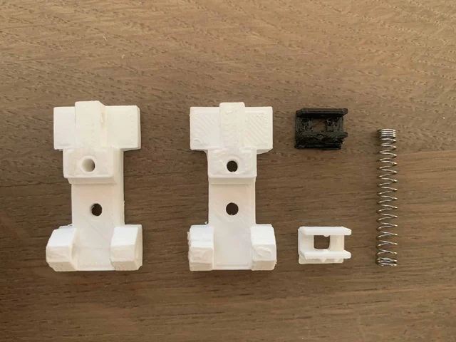
The axes
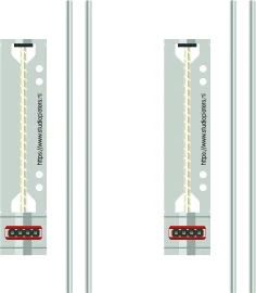
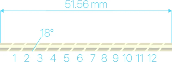
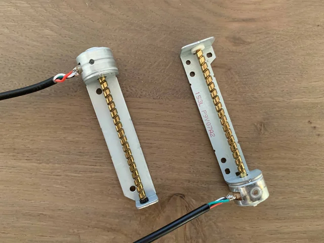
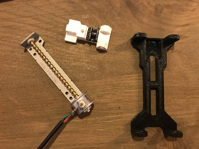
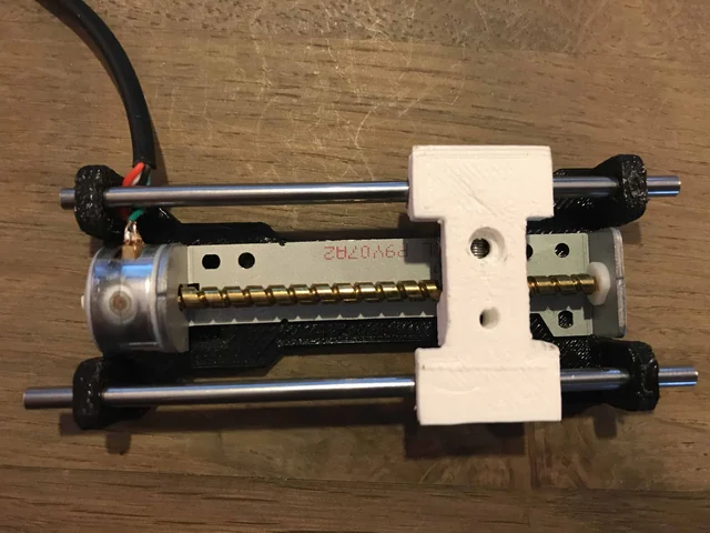
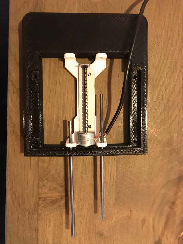
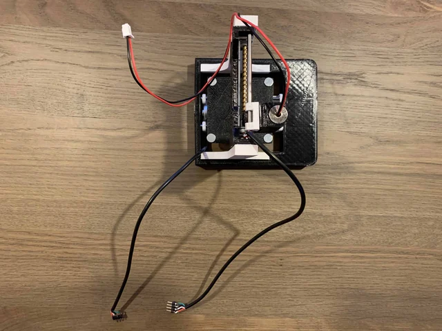
The axes are small stepper motors with a threaded rod. They are old ones that were at hand, so the specifications are those of the motors that happened to be there. The diagram in the repository gives 18 degrees per step, and a length of 51.56 mm.
The electronics
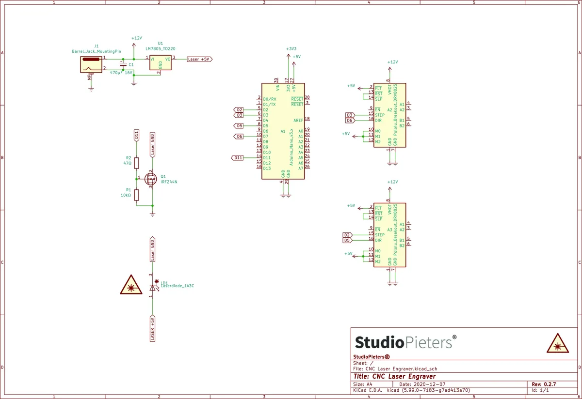
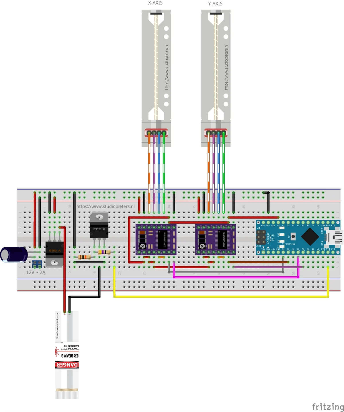
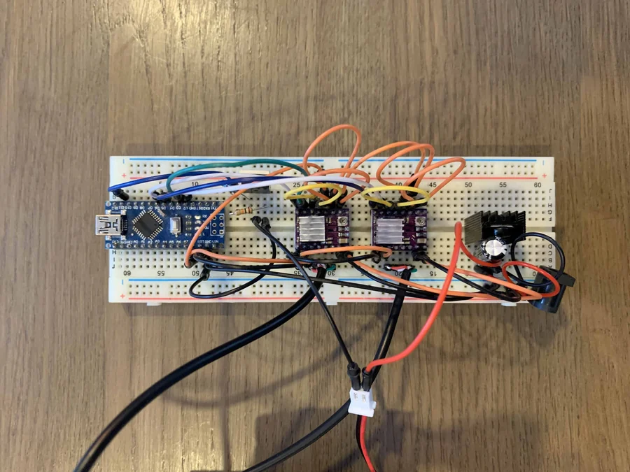
An Arduino Nano runs GRBL, an open-source controller for CNC machines that reads G-code. Driver modules run the two stepper motors, and the laser power is set through the spindle output of GRBL. The repository has the schematic and a breadboard diagram:

Load GRBL on the Nano
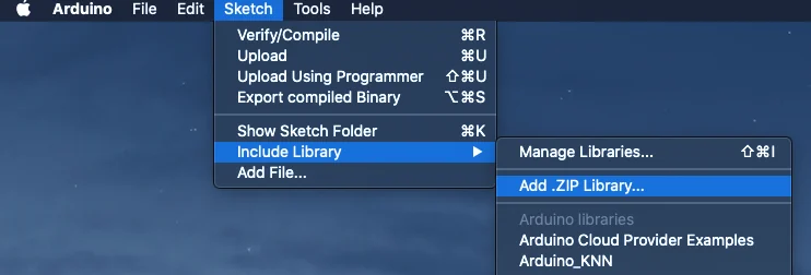
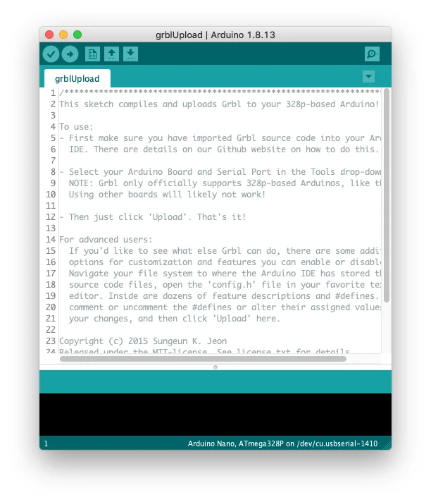
The firmware is GRBL 1.1h. The steps in the screenshots:
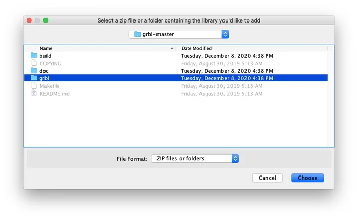
- In the Arduino IDE, choose Sketch, Include Library, Add .ZIP Library.
- Select the folder or the ZIP of the GRBL library.
- Open the
grblUploadexample that comes with the library and upload it to the Nano.
Control it with Universal Gcode Sender
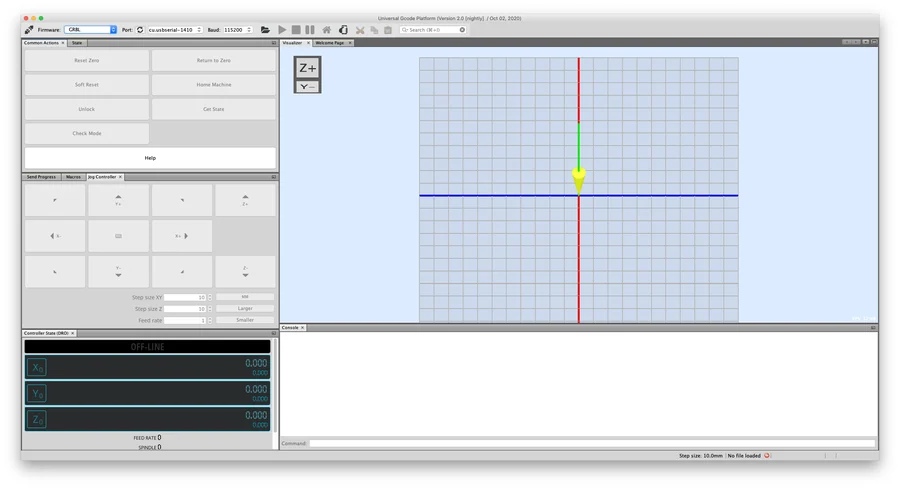
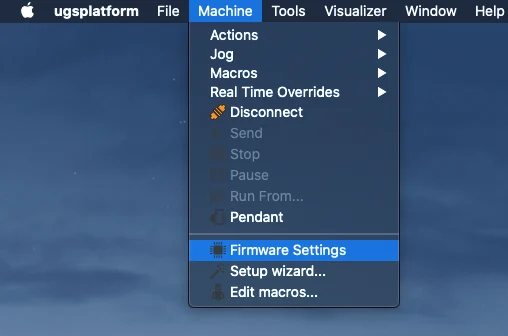
Universal Gcode Sender (UGS) sends G-code to GRBL and lets you jog the axes. Under Machine, Firmware Settings, you find the GRBL settings.
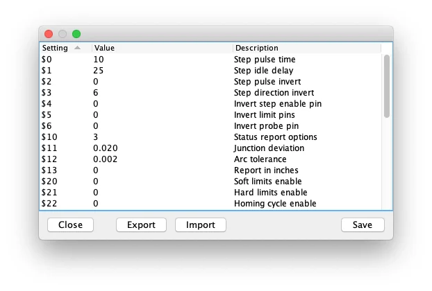
The exported settings in the repository (firmware.settings, from 2 December 2020) show a few values that matter for a laser:
| Setting | Value | Meaning |
|---|---|---|
| $30 | 1000 | Maximum spindle speed, which is 100 % power on the laser output |
| $31 | 0 | Minimum spindle speed |
| $32 | 0 | Laser mode is off |
| $11 | 0.020 mm | Junction deviation, 0.010 mm in the older export |
For engraving, the GRBL documentation advises to turn laser mode on with $32=1, so that the laser does not stop between moves when its power changes. The values can be adjusted, and they are worth checking on your own build.
The G-code files
The repository has five G-code files, Logo.nc, IronMan_helmet.nc, iron-man.nc, Lego_Mini_figure.nc and Stormtrooper.nc. They control the laser power through the S value of every move, so a picture with light and dark parts becomes a burn with a strong and a weak beam. A file starts like this:
G90 (use absolute coordinates)
M3 S0
F2000
G0 X15.333 Y2.667 S0
G1 X16 S3
X16.333 S15
What came out of it
The engraver worked as a machine: the axes move, GRBL takes the G-code. As an engraver it did not work. The laser module was not strong enough, and on wood it left only some small burn marks, and no result worth showing. No resolution was reached.
What this project shows is the whole chain from a printed frame to a laser on a piece of wood. A stronger laser would be the next step, and with it a proper enclosure and eyewear.
Good to know
- The repository holds the STL and STEP files of the frame, the G-code files, the GRBL settings and the images, and is under the MIT licence.
The project is in the CNC-Mini-Laser-Engraver repository on GitHub.
Related
 Tools
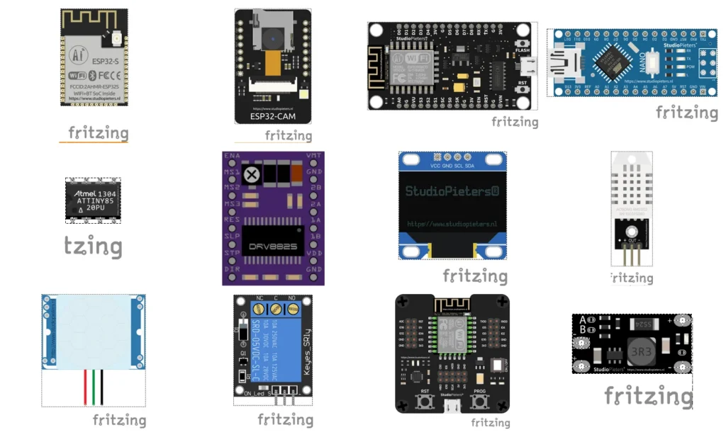
Custom Fritzing Parts for ESP32, ESP8266 and More
About 40 custom Fritzing parts for the boards and modules used at StudioPieters, from the ESP32 to the DRV8825, free to use under a CC BY-NC-ND licence.
Read more
Tools
Custom Fritzing Parts for ESP32, ESP8266 and More
About 40 custom Fritzing parts for the boards and modules used at StudioPieters, from the ESP32 to the DRV8825, free to use under a CC BY-NC-ND licence.
Read more
 Software
Run Homebridge as a Service at Boot
A template init script that starts, stops and restarts a Homebridge server as a service on a Linux computer such as a Raspberry Pi.
Read more
Software
Run Homebridge as a Service at Boot
A template init script that starts, stops and restarts a Homebridge server as a service on a Linux computer such as a Raspberry Pi.
Read more
 Electronics
Arduino Capacitive Buttons
Sometimes the magic isn’t in complex components, but in how cleverly you use the basics. Did you know you can create capacitive touch buttons using nothing more than a resistor, a bit of metal, and an Arduino?
Read more
Electronics
Arduino Capacitive Buttons
Sometimes the magic isn’t in complex components, but in how cleverly you use the basics. Did you know you can create capacitive touch buttons using nothing more than a resistor, a bit of metal, and an Arduino?
Read more
More projects
Keep building.
Electronics, 3D printing and CNC builds, documented from the first idea to the last screw.
All projects