If you’re a maker, designer or an engineer, chances are you’ll need to make a custom worm wheel at some point. This might be a simple worm wheel to drive some gear for Higher torque output. With Autodesk® Fusion 360 software and a desktop 3D printer, you can create a custom Worm wheel.
Worm Gear
Worm gears are usually used when large speed reductions are needed. The reduction ratio is determined by the number of starts of the worm and number of teeth on the worm gear. But worm wheels have sliding contact which is quiet but tends to produce heat and have relatively low transmission efficiency.
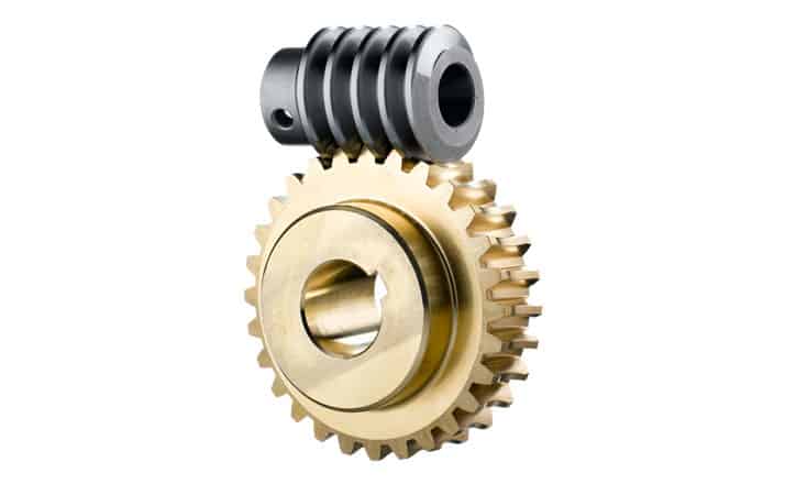
As for the materials for production, in general, worm is made of hard metal while the worm wheel is made from relatively soft metal such as aluminium bronze. This is because the number of teeth on the worm gear is relatively high compared to worm with its number of starts being usually 1 to 4, by reducing the worm gear hardness, the friction on the worm teeth is reduced. Another characteristic of worm manufacturing is the need of specialized machine for gear cutting and tooth grinding of worms. The worm gear, on the other hand, may be made with the hobbing machine used for spur gears. But because of the different tooth shape, it is not possible to cut several gears at once by stacking the gear blanks as can be done with spur gears.
For this blog I made a Small video tutorial:
Printing the Model
When you are using a 3D printer, I would advise to use the highest print settings. I use Ultimaker Cura software you can download it here for Free!
Layer height
The layer height is one of the most frequently changed settings. It is the thickness of one printed layer in millimetres. With a thinner layer height you can increase the quality of the print, leading to a smoother surface and more detail visible in the Z-direction (height) of the model. On the other hand, by using thicker layers you can decrease the print time substantially.