The ESPC2-02 is a compact, powerful Wi-Fi and Bluetooth 5.0 module built around Espressif’s ESP8684/ESP32-C2 SoC. Designed for low-power connected devices, it delivers impressive performance in a remarkably small form factor. Whether you’re designing smart lighting, wireless sensors, mesh networks, or industrial IoT systems, the ESPC2-02 provides a feature set that rivals larger modules—while remaining cost-effective and easy to integrate. This guide walks you through everything you need to know about the ESPC2-02 pinout, written in the same clear, structured style as the world’s best hardware manuals.
What Is the ESPC2-02?
System-on-Chip (SoC)
At its core, the ESPC2-02 uses the ESP8684—a highly integrated Wi-Fi and Bluetooth LE 5 SoC. It features:
- 32-bit RISC CPU
- 2 MB embedded flash
- 576 KB ROM
- 272 KB SRAM
- Integrated 2.4 GHz RF
- Full Wi-Fi 802.11 b/g/n support
- Bluetooth LE 5 (1M, 2M, 500K, 125K modes)
This makes the ESPC2-02 ideal for low-power applications without sacrificing wireless performance.
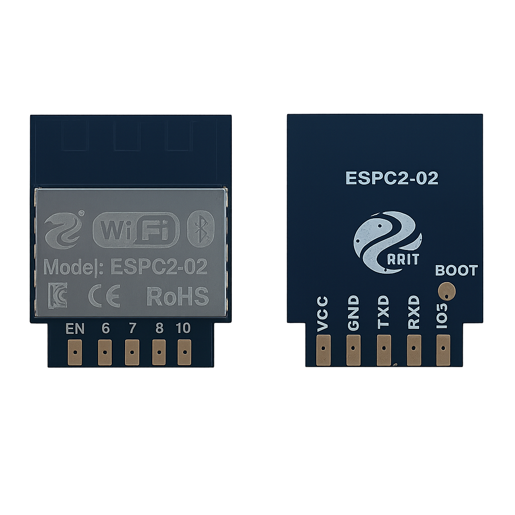
Module
The module package measures only 15 × 17.3 × 3 mm and includes:
- PCB antenna
- RF matching network
- 26 MHz crystal
- Power regulation
- Embedded flash
- Breakout for I/O pins
Real-World Applications
The module is used in:
- Smart plugs and smart LED systems
- Wi-Fi probes and sniffers
- Mesh networks
- Sensor networks
- Wireless location/beacon systems
- OTT devices
- Industrial field bus systems
Designed for Connectivity and Control
The ESPC2-02 offers a rich set of wireless and peripheral capabilities:
Wi-Fi (802.11 b/g/n)
- Operates from 2412–2484 MHz
- Up to 72.2 Mbps
- Supports STA, Soft-AP, STA+AP, and promiscuous mode
- 3 virtual Wi-Fi interfaces
Bluetooth LE 5
- 125 Kbps to 2 Mbps
- Advertising extensions
- Multiple advertising sets
- Channel Selection Algorithm
Peripheral Interfaces
- 8 GPIO pins
- UART
- I²C
- SPI
- PWM
- ADC
- EN (Enable) pin
Power Features
- Active Wi-Fi TX peak: >400 mA
- Modem-sleep: ~15 mA
- Light-sleep: ~140 µA
- Deep-sleep: ~5 µA
Recommended power supply: ≥ 500 mA (datasheet p.6).
ESPC2-02 Pinout — GPIO Fundamentals

Pinout Overview
| Pin | Name | Type | Function | Additional Functions |
|---|---|---|---|---|
| 1 | EN | I/O | Chip enable (HIGH = on) | Internal pull-up |
| 2 | IO6 | I/O | GPIO6 | MTCK, FSPI CLK |
| 3 | IO7 | I/O | GPIO7 | MTDO, FSPI D |
| 4 | IO10 | I/O | GPIO10 | FSPI CS0 |
| 5 | IO18 | I/O | GPIO18 | General-purpose |
| 6 | IO4 | I/O | GPIO4 | ADC1_CH4, MTMS, FSPIHD |
| 7 | IO5 | I/O | GPIO5 | MTDI, FSPIWP |
| 8 | TX0 | I/O | GPIO20 | UART0 TX |
| 9 | RX0 | I/O | GPIO19 | UART0 RX |
| 10 | GND | P | Ground | — |
| 11 | VCC | P | 3.3V input | 500 mA recommended |
Boot Mode Pins
| Mode | IO9 Level | Description |
|---|---|---|
| UART Download Mode | LOW | Flash programming mode |
| Flash Boot Mode | HIGH (default) | Normal operation |
Although IO9 is not broken out, it controls how the module boots internally.
Advanced GPIO Features
Analog-to-Digital Converter (ADC)
The module has one ADC pin:
- GPIO4 → ADC1_CH4
Suitable for:
- Potentiometers
- Light sensors
- Thermistors
- Battery monitoring
UART (Programming Interface)
- TX0 → GPIO20
- RX0 → GPIO19
Used for:
- Programming (UART Download Mode)
- Serial debugging
- Communication with external systems
SPI Interface
FSPI signals are exposed, but must be used carefully because they relate to flash access:
- GPIO6 → FSPI CLK
- GPIO7 → FSPI D
- GPIO10 → FSPI CS0
- GPIO5 → FSPI WP
- GPIO4 → FSPI HD
Use them only if your firmware does not interfere with flash operations.
I²C Communication
Any GPIO can be used as bit-banged (software) I²C.
Recommended pair:
- SDA → IO4
- SCL → IO5
PWM
All GPIOs support PWM using the LEDC engine.
Use cases:
- LED dimming
- Motor control
- Audio signal generation
Recommended Design Practices
(Derived from datasheet chapters 8–11)
✔ Keep the antenna area clear
Place the module at the PCB edge. Avoid:
- ground pour
- metal chassis
- shielding
- dense routing
(See figure 9.1 in datasheet.)
✔ Add decoupling capacitors
Use 22 µF + 0.1 µF close to VCC.
✔ Ensure power stability
Because Wi-Fi peaks exceed 400 mA, the supply must deliver ≥ 500 mA comfortably.
✔ Use series resistors on high-speed lines
10–100 Ω recommended to reduce EMI and ESD.
✔ Respect I/O current limits
Max 40 mA per GPIO.
How to Program the ESPC2-02
Required Connections
- TX0 ↔ RX of USB-UART converter
- RX0 ↔ TX of USB-UART converter
- EN → pulled HIGH
- IO9 LOW → reset → enter flash mode
- Stable 3.3V supply
Steps
- Pull IO9 LOW and reset the module to enter UART download mode.
- Connect via USB-UART.
- Select ESP32-C2 in Arduino IDE or ESP-IDF.
- Upload firmware.
Firmware updates are officially done using UART Download Mode
Minimum System Design
Essential components:
- ESPC2-02 module
- 3.3V regulator
- 22 µF + 0.1 µF decoupling
- UART connections
- EN pin tied HIGH
- BOOT selection via IO9
This forms the smallest working ESPC2-02 system.
Conclusion — Designed for What’s Next
The ESPC2-02 is a highly capable, ultra-compact wireless module combining Wi-Fi 802.11 b/g/n, Bluetooth LE 5, and a versatile peripheral set within a tiny footprint. Its low power consumption, integrated flash, and flexible GPIO architecture make it perfect for next-generation IoT devices—from smart home systems to industrial automation and sensor networks. Mastering the ESPC2-02 pinout gives you everything you need to build powerful, efficient, and scalable wireless devices.