The Wemos S2 Mini is a compact ESP32-S2 development board tailored for modern USB-powered IoT applications. With a small footprint, native USB, and full GPIO breakout, this purple powerhouse offers just the right balance between functionality and minimalism. In this guide, we’ll take a deep dive into the S2 Mini pinout, helping you master every feature of this efficient board. It is also ideal for developing on of my homekit accessory.
What is the S2 Mini?
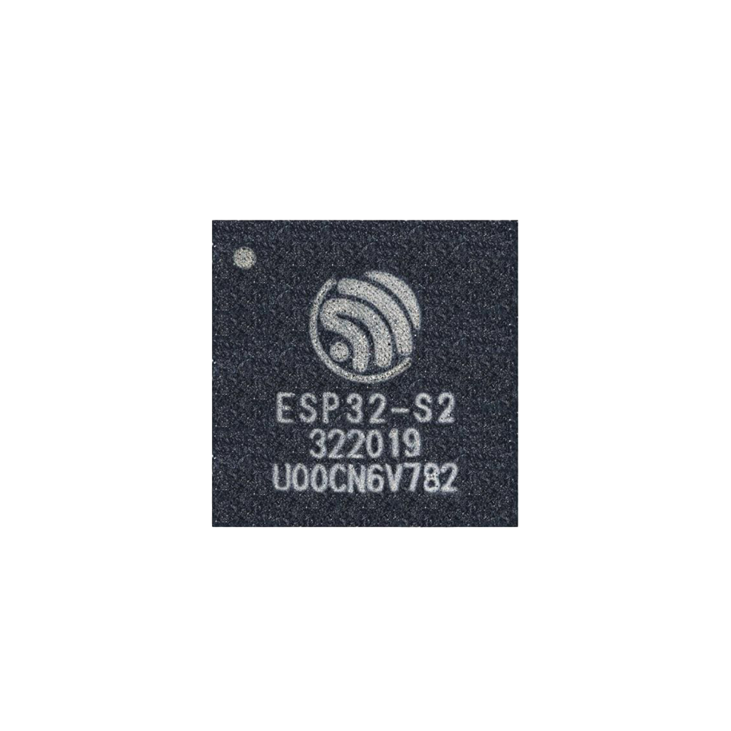
System-on-Chip (SoC):
At its core, the ESP32-S2 is a single-core 32-bit Xtensa LX7 chip running at 240 MHz, developed by Espressif. It includes native USB, Wi-Fi 802.11 b/g/n, a 43-GPIO matrix, touch sensing, ADC, and secure boot, making it ideal for smart sensors, USB gadgets, and low-power IoT nodes.
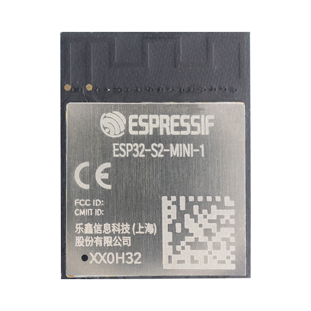
Module:
The S2 Mini integrates the ESP32-S2 directly on the PCB with onboard flash and USB connectivity. It’s manufactured by WEMOS/Lolin, known for their clean, efficient board designs.
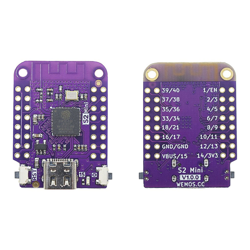
Development Board (DevKit):
The S2 Mini offers USB-C, a reset button, 3.3V regulator, and 29 accessible GPIOs across clearly labeled headers — all in a tiny footprint perfect for breadboards or embedded projects.
Designed for Compact Power
With onboard USB and modern features, the S2 Mini provides:
- 240 MHz single-core Xtensa LX7 CPU
- Wi-Fi 802.11 b/g/n
- 43 total GPIOs (29 broken out)
- 14 capacitive touch sensors
- Native USB 1.1 (Device and Host)
- 2 × 12-bit ADCs
- 20 PWM channels
- SPI, I2C, UART, I2S, RMT, DAC
- On-chip temperature sensor
- 4 MB flash (varies by revision)

** The ESP32 pinout is available for download at the end of this post in high resolution – for free!
S2 Mini Pinout – GPIO Fundamentals
The S2 Mini breaks out 29 GPIOs on 2 rows of headers. Every pin supports digital I/O, and most are multiplexed for other functions like I2C, SPI, UART, ADC, or touch sensing.
Touch Sensing
The ESP32-S2 includes 14 capacitive touch sensors, ideal for buttonless interaction or gesture sensing.
- Touch GPIOs: GPIO1–14
Applications: Touch sliders, buttons, motion detection, etc.
Analog Input (ADC)
Two ADCs provide up to 20 channels with 12-bit resolution.
- ADC1 Channels: GPIO1–10
- ADC2 Channels: GPIO11–20
Tip: Use ADC1 for analog reads when Wi-Fi is active (ADC2 shares Wi-Fi resources).
PWM (Pulse Width Modulation)
Up to 20 PWM channels are available. All GPIO’s on the S2 Mini support PWM, so you can use any pin for dimming LED’s, servo motors, or sound generation. But not every pin on the module is equally suitable for PWM due to overlap with other functions (such as USB, bootstraps, etc.).
I2C and SPI Communication
I2C
Software-assignable, but common default:
- SDA – GPIO8
- SCL – GPIO9
Use Wire.begin(SDA, SCL); to customize.

SPI
Software-assignable, typical config:
- MOSI – GPIO35
- MISO – GPIO37
- SCLK – GPIO36
- CS – GPIO34

S2 Mini GPIO Quick Reference Table
| GPIO | Special Function | ADC | DAC | Touch | RTC | Boot State / Notes |
|---|---|---|---|---|---|---|
| 0 | Boot, Strapping | No | No | No | Yes | Pull LOW to enter bootloader |
| 1 | Touch, ADC1 | ADC1_0 | No | Yes | Yes | – |
| 2 | Touch, ADC1 | ADC1_1 | No | Yes | Yes | – |
| 3 | Touch, ADC1 | ADC1_2 | No | Yes | Yes | – |
| 4 | Touch, ADC1 | ADC1_3 | No | Yes | Yes | – |
| 5 | Touch, ADC1 | ADC1_4 | No | Yes | Yes | – |
| 6 | Touch, ADC1 | ADC1_5 | No | Yes | Yes | – |
| 7 | Touch, ADC1 | ADC1_6 | No | Yes | Yes | – |
| 8 | Touch, ADC1, I2C SDA | ADC1_7 | No | Yes | Yes | Common default: I2C SDA |
| 9 | Touch, ADC1, I2C SCL | ADC1_8 | No | Yes | Yes | Common default: I2C SCL |
| 10 | Touch, ADC2 | ADC2_0 | No | Yes | Yes | – |
| 11 | Touch, ADC2 | ADC2_1 | No | Yes | Yes | – |
| 12 | Touch, ADC2 | ADC2_2 | No | Yes | Yes | – |
| 13 | Touch, ADC2 | ADC2_3 | No | Yes | Yes | – |
| 14 | Touch, ADC2 | ADC2_4 | No | Yes | Yes | – |
| 15 | XTAL_32K_P, LED | No | No | No | No | Onboard LED |
| 16 | XTAL_32K_N | No | No | No | No | – |
| 17 | DAC1, ADC2 | ADC2_6 | Yes | No | No | – |
| 18 | DAC2, ADC2 | ADC2_7 | Yes | No | No | – |
| 19 | ADC2 | ADC2_8 | No | No | No | Not USB D+ |
| 20 | ADC2 | ADC2_9 | No | No | No | Not USB D− |
| 21 | General I/O | No | No | No | No | – |
| 33 | General I/O | No | No | No | No | – |
| 34 | SPI CS | No | No | No | No | SPI default CS |
| 35 | SPI MOSI | No | No | No | No | SPI default MOSI |
| 36 | SPI CLK | No | No | No | No | SPI default CLK |
| 37 | SPI MISO | No | No | No | No | SPI default MISO |
| 38 | General I/O | No | No | No | No | – |
| 39 | JTAG MTCK | No | No | No | No | Debug function |
| 40 | JTAG MTDO | No | No | No | No | Debug function |
| 43 | UART0 TX (not broken out) | No | No | No | No | Available internally only |
| 44 | UART0 RX (not broken out) | No | No | No | No | Available internally only |
Best Practices and Common Mistakes
- Don’t pull GPIO0 HIGH during boot if you want to flash firmware.
- Avoid using ADC2 for analog reads while Wi-Fi is active.
- Use pull-up/down resistors for floating inputs.
- Keep current draw below 12mA per GPIO.
- Make sure to debounce any mechanical buttons.
How to Program the S2 Mini
Development Environments
- ESP32-Homekit – My Own repository
- Arduino IDE – with ESP32-S2 board package
- PlatformIO – highly recommended
- ESP-IDF – official low-level SDK from Espressif
Flashing and Programming
| Function | Pin | Description |
|---|---|---|
| EN | EN pin | Reset the board |
| IO0 | GPIO0 | Hold LOW to enter bootloader |
Steps:
- Connect the USB-C cable.
- Select ESP32-S2 Dev Module in Arduino/PlatformIO.
- Click upload. Hold BOOT if needed during flashing.
Conclusion: Tiny, Modern, and USB-Ready
The S2 Mini is a minimal but mighty development board. With native USB, full GPIO access, and a no-nonsense design, it’s ideal for compact IoT projects, wearable devices, and USB-powered tools. Mastering its pinout gives you the confidence to build faster and better.
Happy Building!
Download the ESP32- S2 pinout here in high resolution – for free*!
* Free to use under the MIT license — attribution is required.