
Electronics
Building a micro-Duck, Part 6: Changing Course, and Testing Before I Buy
The route changed again. Why I dropped the first plan, what I checked in the circuit board files before spending money, and the small bench test I'll do first.
- 14 min read
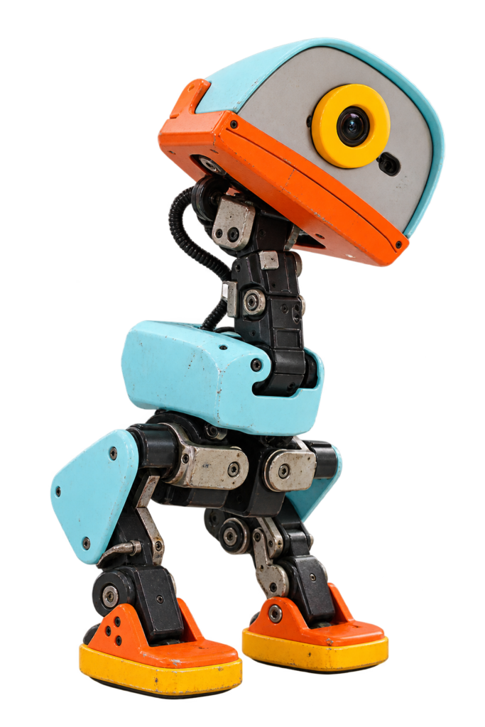
In Part 5 I wrote: “I haven’t built this duck yet.” That is still true. Nothing is built, and nothing is ordered.
But something did change: the route. I told you Part 6 would be about unpacking parts and setting servo IDs. That can’t happen, because no parts have arrived. So this part is different. It’s about why I changed course again, what I checked before spending money, and the small test I’m going to do first.
I know it’s annoying when someone changes plans in the middle of a series. I’d rather tell you than act as if nothing happened. This is a build log, and a log includes the turns that didn’t go as planned.
I’d like you to walk this road with me, so I’ll keep it simple and explain every new word. If something is unclear, tell me. Maybe you already know a part of this better than I do.
Safety first
We don’t build anything in this part, but the rules are the same as always, and the next parts need them:
- Batteries (lithium): a short circuit can cause a fire. Never connect a battery before you have checked the cables with a multimeter. Never charge a battery without watching it.
- Plus and minus: if you swap them, parts can break at once. Check twice.
- Soldering iron: it’s very hot. Put it in its stand, never on the table.
- Order of work: first check, then power. Always.
What happened after Part 5
Three things came together.
1. The seller told me delivery abroad is hard. On 7 November, kissqy wrote in issue #11 that sending to other countries is difficult because of export control. That matters, because his ready-made HAT, IMU board and HUB are the heart of his build.
2. I still had no way to get a HUB. In Part 5 I planned to message the seller. I had no confirmed place to buy this board, and without it I can’t build the duck.
3. I realised the route isn’t for everybody. I want this series to work for beginners, from young to old. A route that needs an agent, a forwarding service and a seller who may not be able to ship is not that.
So I changed my own requirements. Parts may come from AliExpress, as long as I don’t need strange tricks. And there is one rule that now outweighs everything else: I want Pollen’s software. I care about that more than about using only off-the-shelf hardware.
Not confirmed
I don’t know yet if kissqy can ship to the Netherlands. I only know what he wrote in the issue. I haven’t asked him again.
Three words before we go on
I use these a lot in the next parts, so let me explain them now.
Printed circuit board (PCB). The flat, green or black board with thin copper lines, inside almost every electronic device. Think of it as a road map for electricity: the lines are the roads, and the parts are the buildings that sit along them.
Gerber files. The files you send to a factory so it can make your PCB. Think of it as the printing file for a book. The factory doesn’t need to understand the story, it only needs to know where every line goes.
BOM (bill of materials). The shopping list of a PCB: every small part, with its number and quantity. Think of it as the ingredients list of a recipe.
I also use two words from Part 5: the IMU (the motion sensor that tells the robot how it is tilted) and the HAT (a board that sits on top of the small computer, like a hat).
The new route
Here is where I stand. I split it in what I could verify and what I could not. That split matters, so I’ll keep doing it.
| Piece | What it is | What I can say |
|---|---|---|
| Software and print files | fanhao375’s microduck-replica: a ready-made system image for the Radxa ZERO 3W, plus a CAD set for printing | Verified: it exists, is updated almost daily, and uses Feetech HD-1910 servos. Self-reported only: that it walks. He shows videos from 24 October. I found no one who confirmed it independently. |
| The HAT | Pollen’s own board (Apache-2.0 license) | Verified: the files exist and I checked them (see below). Not tested by me. |
| IMU board, hub, battery board | jyg9’s community kit (CERN-OHL-P license) | Verified: the files exist and I checked them. Not confirmed: that the IMU board works with fanhao375’s image. On paper it should. Nobody has tried. |
Let me be honest about the downsides. As far as I could find, nobody has shown this exact combination working. Parts of the route are not beginner-friendly: some small parts must be soldered by hand, the IMU board needs a special tool (a J-Link, which I’ll explain later) to put its software on the first time, and the documentation is mostly in Chinese. I’m telling you now so that you’re not surprised later.
Then why this route? Because it is the one where Pollen’s software runs on standard servos, it has a system image I can simply put on a memory card, and it is actively maintained. The other candidates I looked at (jyg9’s own software, zhuoligetu123’s and wangtao3343’s forks) are better as sources to learn from than as a base to build on.
What I checked before spending anything
I have KiCad, a free program to design and inspect circuit boards. I ran two automatic checks on the files, with help from an AI assistant:
- DRC (design rules check): does the layout break the factory’s rules, like lines that sit too close together?
- ERC (electrical rules check): does the circuit diagram have loose ends or missing connections?
I only checked the files. I did not check if the circuits do what they should. That needs a real test, and that is what the rest of this part is for.
The HAT (Pollen’s board, version D1)
- No unconnected nets, and the layout matches the circuit diagram.
- The DRC gave 55 messages. 40 of them concern the same connector (the 40-pin header): its positioning holes sit 0.02 mm from the pads, where the rule says 0.15 mm. The other 15 are about missing library files in my copy of KiCad. The factory’s own check should tell me if the 0.02 mm is a problem.
- I compared the factory files with the KiCad source: same size, same layers, same number of holes.
- I checked all capacitors against the supply voltages. No blocking problem. Two things to handle: the value of two small capacitors (C8 and C9) is written as 220 nF in the list, but the part number is a 220 pF part (that is a thousand times smaller). I think the part number is right, but I can’t be sure, so I’ll write the exact part number in the order. And the 10 µF capacitors on the 5 V line have little margin.
- Stock risks: the microphone is shown as both in stock and out of stock on different pages. The audio chip (codec) is marked “not recommended for new designs”, which means it may become hard to buy.
The IMU board (jyg9)
- No unconnected nets, and the layout matches the circuit diagram. The factory files match the source.
- The ERC reported 64 “errors”, but they are tidiness issues (unused pins that aren’t marked as unused), not wrong connections.
- One part (F1) sits in series with the data line and adds a little resistance. I need to measure the signal level on the bus after soldering.
- Biggest risk: it hasn’t been tested together with fanhao375’s system image.
The hub and the battery board (jyg9)
- The hub has a 10 V capacitor on a line that reaches 8.4 V. That is little margin, so I may look for a 16 V version.
- Some copper lines for ground are only 1 mm wide. I can’t say if they get warm until I test under load.
- A cable between the HAT and a Feetech servo needs pin 1 and pin 3 crossed, because the two sides use opposite order for ground and data. A straight cable would connect ground to the data line. This is exactly the kind of mistake that is easy to make, so I’ll check every cable with a multimeter.
The plan: test before I buy everything
This is the part I’m most happy with. Instead of ordering everything and hoping, I go in phases.
Phase A: the bench test. Order only the HAT and the IMU board. When they arrive, connect them to the Radxa on my table, without servos and without the battery on the duck, and see if:
- the system image starts,
- the image recognises my IMU board,
- the numbers from the sensor make sense when I tilt the board.
If this fails, I’ve spent a little and learned a lot. If it works, I order the rest with much more confidence. The biggest risk of the whole route is the IMU board and the image, so I test that first.
Phase B and later: the hub and battery board, the standard parts (servos, Radxa, cables, bearings, screws), and printing. This comes after phase A.
One rule I set for myself
I know how to work with KiCad. I could change these boards. But the duck must walk in the end. So my rule is: keep tested designs unchanged, and only change something when there is no other way. Every change is a new risk that nobody has tested.
The factory quote
I filled in a quote for the HAT at PCBWay: 4 layers, 65 × 30.9 mm, 5 boards, 1.0 mm thick.
PCBWay warned me about one spot: two pads sit 0.15 mm apart. With the matt black solder mask, they need at least 0.22 mm so there can be a small wall of mask between them. They offered three options:
- A: open the mask around those pads, so the area has no wall in between. The board stays black.
- B: cut the copper of the pads back. This changes Pollen’s design.
- C: I change the design file myself.
I chose A, so the copper stays exactly as Pollen made it. The price I pay: a higher risk of tiny solder bridges at that spot. When the board arrives, I will check that spot closely.
I have asked PCBWay for a quote to find out what the boards will cost. I am waiting for their answer, so I can’t give you a price yet. When it arrives, I’ll write it down.
If you want to order your own boards, you can do that at PCBWay (sponsored link).
Status
Nothing is paid and nothing is ordered. When I do order, I’ll write it down in the next part, with the date.
What you can do now, for free
You don’t need to wait for parts. There is one step I’d like us to do together. It’s about trust: if you download a big file from the internet, how do you know that it’s the right file and that nothing went wrong on the way?
Step: check the system image
What do you need?
- A computer.
- The system image from fanhao375’s release page (the
.img.xzfile, about 750 MB) and the small.sha256file next to it.
New word: checksum. A checksum is a fingerprint of a file. If even one tiny thing in the file is different, the fingerprint is completely different. If your fingerprint equals the one on the website, the file is the same.
What are you going to do?
- Download the
.img.xzfile and the.sha256file into one folder. - Open a terminal (on a Mac: the Terminal app; on Windows: Command Prompt).
- On a Mac, type
shasum -a 256followed by the file name, then press Enter. On Windows, typecertutil -hashfilefollowed by the file name andSHA256. - Open the
.sha256file in a text editor. - Compare the two long strings of letters and numbers.
- Do not run or install the file yet. We only check it.
What should it look like? The two strings are exactly the same, character for character.
Does it go wrong?
- The strings are different. The download failed or is damaged. Delete the file and download it again. If it’s different a second time, don’t use it, and write to me.
- The terminal says “file not found”. You’re probably in the wrong folder. Put the files on your desktop and type
cd Desktopfirst. - You see capital letters in one and small letters in the other. That’s fine. Letters can be written both ways. Check the characters.
I have not done this step yet. I’ll do it with you and tell you how it went in Part 7.
The other free things
- ☐ Install a slicer (the program that prepares a model for the printer). I’ll use OrcaSlicer.
- ☐ Read fanhao375’s guide in his repository.
- ☐ Download the CAD files, but don’t print yet.
Where the parts list stands
I haven’t ordered anything, and I’m still checking details, so treat this as a draft. Quantities and variants only, no prices.
| Part | Amount | Remark |
|---|---|---|
| Feetech HD1910M servo | 15 | His list says HD1910M, his CAD file says HD-1910-C001. I’ll check the label when they arrive. |
| Radxa ZERO 3W | 1 | With pin header, no built-in storage |
| microSD card | 1 | Good brand, 32 to 64 GB |
| URT-2 (USB-C to servo bus) | 1 | To set the servo IDs |
| Camera (IMX219, wide angle) | 1 | His list forgets the cable that connects it. I need to add it. |
| Distance sensor (ToF) | 1 | Also needs a cable that isn’t on his list. |
| Speaker | 1 | |
| NP-F550 battery | 1 | His list forgets the charger. |
| Bearings, screws, thread locker | several | Quantities per his list |
| J-Link (programmer) | 1 | Only for the first software upload to the IMU board |
| Multimeter and soldering iron | 1 each |
I’ve marked the three gaps I found in his list. If you spot more, please tell me.
Credits and licenses
This is a personal, non-commercial project, and I’m not affiliated with Pollen Robotics or any of the people below.
- Microduck is a design by Pollen Robotics.
- fanhao375’s system image is free for personal, non-commercial use only. His CAD is CC BY-NC-SA 4.0.
- The HAT is by Pollen Robotics (Apache-2.0).
- jyg9’s boards are CERN-OHL-P.
- kissqy’s HAT, IMU, HUB, console and models, which I used for Part 5, are for personal and non-commercial use only. I’m no longer using them, but I thank him for the guide that helped me understand this robot.
Overview of the series
This is the plan as I see it now. It may shift, and a part is only written after the step is really done.
| Part | Subject | Status |
|---|---|---|
| 1 to 3 | XGO-Duck: plan, parts, print plan | Published, no longer valid |
| 4 | Too many ducks: doubt and research | Published |
| 5 | Starting over: words, safety, tools, printing | Published, partly outdated |
| 6 | Changing course, and testing before I buy | This part |
| 7 | Printing while I wait (fanhao375 set on the Ender 3 V2) | To do |
| 8 | The first circuit boards arrive: check, finish, bench test | To do |
| 9 | Standard parts arrive: unpack servos, set IDs | To do |
| 10 | Building the legs | To do |
| 11 | Body, battery, hub and IMU | To do |
| 12 | Head, neck, Radxa and wiring | To do |
| 13 | Flash the image, Wi-Fi, calibrate | To do |
| 14 | First steps, and what went wrong | To do |
Conclusion: Part 7 Is Printing While I Wait
- Part 7: Printing while I wait. The fanhao375 print set on my Ender 3 V2. I already know that his file and his readme disagree on the number of plates and parts (six plates and 43 objects, against five and 52), so I’ll count everything after I’ve arranged the plates. I’ll also report the system-image check from this post.
- Part 8: The first boards arrive. Check them, finish the soldering, and do the bench test from phase A. Here we find out if the biggest risk is real.
- Part 9: The standard parts arrive. Unpacking the servos and setting their IDs.
- Parts 10 to 14: Legs, body, head, software and the first steps. If something fails, you’ll read about it here.
This plan may shift. If the bench test goes wrong, the whole series changes, and I’ll tell you.
Have you built a Microduck, or have you tried one of these boards? I’d love to hear from you through the contact page. It can save both of us a lot of trouble.
Previous: Part 5: Starting over, the right way
Small duck, big steps. Happy hacking!
Unofficial fan project
Microduck is by Pollen Robotics. This site is not affiliated with Pollen Robotics, fanhao375, jyg9 or kissqy, and none of them endorse this series. PCBWay is a sponsor of Studio Pieters, and the PCBWay link above is a sponsored link.
Related
 Software
Homebridge Plugin for an HTTP Switch
A Homebridge plugin that calls a web address to switch a device on and off, and shows it as a switch in the Home app.
Read more
 3D printing
Nest Protect Ceiling Mounting Ring
Sometimes the biggest challenges come from the smallest details. The Nest Protect (2nd Generation) is a beautiful piece of hardware, a combined smoke and CO alarm, that comes in two versions: battery powered and 220V wired.
Read more
 Electronics
Temperature and Humidity for Homebridge with an ESP-01
An ESP-01 with a DHT11 that answers a web request with the temperature and humidity as JSON, for Homebridge.
Read more
More projects
Keep building.
Electronics, 3D printing and CNC builds, documented from the first idea to the last screw.
All projects