
HomeKit
HomeKit LED Strip Using 3 Standard Modules
* This project is featured on Instructables
- HomeKit
- Safety notes
- 8 min read
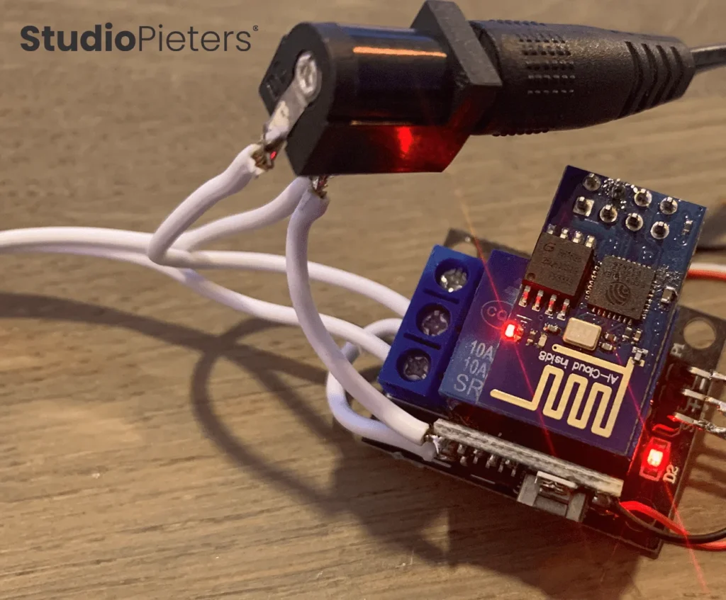
*This project is featured on Instructables
Most of the HomeKit builds on this site use a full ESP32 or ESP8266 dev board, but plenty of people start with whatever’s already in a parts bin. This guide was written specifically for beginners and hobbyists: a HomeKit-controlled LED strip built from three genuinely “standard” modules, a bare ESP8266-01S, a small buck converter, and a relay, nothing exotic, nothing surface-mount.
What You'll Build
By the end of this guide, a single-color 12V LED strip will switch on and off from the Apple Home app or Siri, powered from a normal 12V adapter, with no cloud account and no vendor app. Because the circuit only switches power on and off (via a relay), it works with a plain white or single-color strip, not an addressable/RGB strip, those need a completely different, data-driven approach (see the WS2812B (NeoPixel) guide on this site instead).
This is a genuinely beginner-friendly build. Every wire, every command, and every setting screen below is spelled out.
Difficulty Level
Rating: 2 / 5 Soldering Irons, beginner friendly.
No advanced electronics background needed, but you should be comfortable with:
- Basic through-hole soldering
- Using a multimeter to check a voltage
- Typing commands into a Terminal window
The Three Modules
The whole circuit comes down to three off-the-shelf modules between the wall adapter and the LED strip:
| Module | What it does |
|---|---|
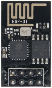
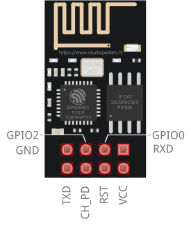
| ESP8266-01S | Brain of the accessory. A tiny WiFi/TCP module with only 2 usable GPIO pins plus serial RX/TX, but the full WiFi and TCP/IP stack is already built in. The newer black “01S” revision has 1MB of flash (the original blue ESP-01 only had 512KB), 1MB is what this build needs for HomeKit firmware. |
| P2307 buck converter (“Mini 360”) | Steps the 12V supply down to the 3.3V the ESP8266-01S needs. Uses an integrated power inductor and synchronous rectifier chip, small and efficient. |
| SRD-05VDC-SL-C relay | Switches the LED strip’s actual 12V power. It has three high-voltage screw terminals (NC, C, NO) for the strip’s power, and three low-voltage pins (GND, VCC, Signal) wired to the ESP8266. A HIGH signal from the ESP energizes the relay’s internal electromagnet, opening or closing the high-voltage contacts. |
And the strip itself: this build uses a 12V, single-color, IP67-rated white LED strip, IP67 also makes it safe for outdoor use.
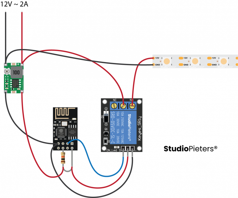
Circuit Diagram
Here’s the full signal path, from wall adapter to light:
- A 12V power adapter feeds the circuit and the LED strip directly.
- The P2307 buck converter taps that same 12V and steps it down to 3.3V to power the ESP8266-01S.
- The ESP8266-01S drives the SRD-05VDC-SL-C relay’s signal pin, which switches the LED strip’s 12V power on or off.
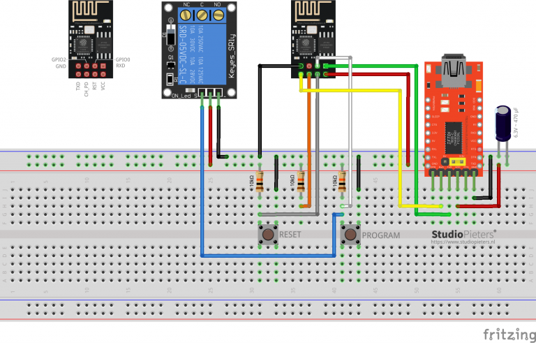
Flashing an ESP8266 is a bit more involved than flashing an Arduino: an Arduino resets itself automatically over its USB/FTDI connection, but the ESP8266 needs GPIO0 pulled to ground and the chip reset while it’s held there, to actually enter flashing mode.
ESP8266-01S Program Scheme
To flash the bare module you’ll need an FTDI (USB-serial) programmer with an onboard voltage regulator.
Before you connect anything: make sure the FTDI adapter’s voltage jumper is set to 3.3V, not 5V. The ESP8266-01S is a 3.3V-only module, leaving the jumper on 5V will destroy it.
This build adds two push buttons to make flashing easier:
- The left button is wired to RESET: pressed, it grounds the RESET pin; released, a pull-up resistor returns it to VCC.
- The right button is wired to PROGRAM (GPIO0): same idea, grounds the pin when pressed, pulled back to VCC through a resistor when released.
An LED is also wired in: it’s on while the ESP8266 is in its programming state, and off during normal operation. With those two buttons, you can put the module into any state you need:
| Mode | How |
|---|---|
| Normal | Both buttons released |
| Reset | Press and release the Reset button |
| Flash mode | Press both buttons, release Reset first, then release Program |
Software Preparation
1. Install esptool.py
You’ll need Python 3.9 or newer. Then, in a Terminal window:
pip install esptoolIf that doesn’t work on your system, try one of these instead:
pip3 install esptoolpython -m pip install esptoolpip2 install esptoolVerify it’s installed:
esptool.py2. Download the LCM2 + ESP-Open-RTOS bin files
Like every other ESP8266 HomeKit accessory on this site, this one runs ESP-Open-RTOS (a community-built, open-source FreeRTOS framework for the ESP8266) plus Life Cycle Manager 2 (LCM) for WiFi setup and OTA updates. You’ll need three files in one folder (e.g. your Downloads folder):
| File | Version |
|---|---|
| otaboot.bin | 2.1.2 |
| rboot.bin | 1.4.2 |
| blank_config.bin | 1.4.2 |
Flashing the ESP8266-01S
Put your module into Flash Mode (press both buttons, release Reset, then release Program), open a Terminal window, and go to the folder with your three .bin files.
Erase the flash first:
esptool.py erase_flashThen write the three files. Replace the port with whatever ls /dev/tty.* shows for your adapter:
esptool.py -p /dev/cu.usbserial-XXXXXXXX --baud 115200 write_flash -fs 1MB -fm dout -ff 40m 0x0 rboot.bin 0x1000 blank_config.bin 0x2000 otaboot.binConnecting to Life Cycle Manager 2
Once flashed, reset the module by pressing the Reset button. It will now broadcast its own WiFi network so you can hand it your real WiFi credentials.
- On your Mac, click the WiFi icon and join the network named LCM-XXXXXX.
- A captive portal opens automatically, listing the WiFi networks the device found nearby.
- Select your own home WiFi network and enter its password. Don’t tap Join yet.
- Optionally set a led_pin for visual feedback, pick the GPIO pin your status LED is wired to (default is GPIO2), and tick “active on 1” if needed.
- Set the OTA repository field to:
AchimPieters/ESP8266-HomeKit-Essentials-Lightstrip - Set the OTA binary file field to:
main.bin - Now tap Join, and wait, this takes about 7 minutes. The device won’t respond to anything while it installs.
When it’s done, the LED lights up for a couple of seconds, and the device is ready to add to HomeKit.
Heads up: the OTA repository can’t be changed later without erasing and re-flashing from scratch, so double-check the spelling before tapping Join.
Pair with Apple Home
- Open the Home app on your iPhone or iPad.
- Tap Add Accessory.
- Scan the QR code the device generates after installation.
- Name your accessory and assign it to a room.
Let's Start Building
With the ESP8266-01S already flashed and paired, it’s time to wire everything together permanently. Take it slow, this is the step where a wrong connection can actually damage the module.
1. Wire the ESP8266-01S
- Solder a red wire to the VCC pin.
- Solder a black wire to the GND pin.
- Solder a white wire to GPIO0.
- Solder a 10kΩ resistor to the CH_PD pin, then bend its other leg over to the VCC pin and solder it there too (this pulls CH_PD high, which the ESP8266 needs to run normally).
Cover the exposed joints with heat-shrink tubing so nothing can short against the case or against itself. No heat gun? The tip of your soldering iron will shrink it too, just keep it moving so you don’t scorch the tubing.
Once insulated, stick the ESP8266-01S onto the relay module with double-sided tape.
2. Wire the buck converter
- On the output side of the P2307 buck converter, solder a red wire to VCC-out and a black wire to GND-out.
- Stick the buck converter onto the relay module with double-sided tape.
3. Wire the relay and power
- Connect the buck converter’s VCC-out wire to the middle screw of the relay’s high-voltage terminal (add one extra wire here too, you’ll need it for the power plug).
- Solder the buck converter’s red VCC wire to the relay’s VCC pin, and its black GND wire to the relay’s GND pin.
- Connect the LED strip’s 12V wire to the relay’s screw terminal.
- Solder the relay screw terminal’s middle wire to the power plug’s VCC.
- Solder the LED strip’s GND wire together with the buck converter’s GND wire, and connect both to the power plug’s GND.
Don’t connect the red VCC and black GND wires to the ESP8266-01S module yet. The buck converter has to be calibrated first, see the next step, connecting an uncalibrated 3.3V-only module to the wrong voltage will destroy it.
4. Calibrate the buck converter to 3.3V
- Plug in the 12V power adapter (with the ESP8266-01S still disconnected).
- Connect a multimeter to the buck converter’s output wires.
- Turn the converter’s trim-pot until the multimeter reads exactly 3.3V.
5. Connect the ESP8266-01S
Once the buck converter is calibrated to 3.3V, solder its red output wire to the ESP8266-01S’s VCC pin, and its black output wire to the ESP8266-01S’s GND pin. Plug the 12V power supply back in, and your own HomeKit LED strip is ready to use.
Full Build Instructions
The original write-up on Instructables has the full photo set for every soldering step above:
HomeKit LED Strip Using 3 Standard Modules on Instructables ›
Related
 HomeKit
ESP8266 HomeKit Garden Light
An outdoor light fitting as a HomeKit accessory: a relay for the standard E14 lamp on mains voltage and a NeoPixel strip for coloured ambience light, on a board left over from the fountain project.
Read more
HomeKit
ESP8266 HomeKit Garden Light
An outdoor light fitting as a HomeKit accessory: a relay for the standard E14 lamp on mains voltage and a NeoPixel strip for coloured ambience light, on a board left over from the fountain project.
Read more
 HomeKit
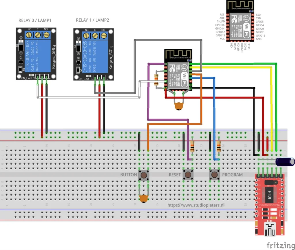
ESP8266 HomeKit Dual Lamps
Two lamps in one light fitting as one HomeKit accessory: a top light and a bottom light, two relays and a button that steps through the combinations. A test setup on an ESP8266.
Read more
HomeKit
ESP8266 HomeKit Dual Lamps
Two lamps in one light fitting as one HomeKit accessory: a top light and a bottom light, two relays and a button that steps through the combinations. A test setup on an ESP8266.
Read more
 HomeKit
ESP32 Power Plug with Energy Meter
For many years, the Dutch retailer Action has sold affordable smart‑home devices under the LSC Smart Connect brand.
Read more
HomeKit
ESP32 Power Plug with Energy Meter
For many years, the Dutch retailer Action has sold affordable smart‑home devices under the LSC Smart Connect brand.
Read more
More HomeKit
Keep building.
Switches, sensors, plugs and blinds: more accessories that you build yourself and add to the Home app.
All HomeKit