The HC-05 Bluetooth module is one of the most widely used serial communication modules for microcontroller-based projects. Designed for versatility, it supports both master and slave modes, making it a reliable and flexible choice for wireless communication. Whether you’re building a remote control, a wireless sensor network, or a Bluetooth interface for your Arduino, the HC-05 has you covered. In this guide, you’ll learn everything about the HC-05 pinout.
What is the HC-05?
Bluetooth Serial Module
The HC-05 is a serial Bluetooth module developed for transparent wireless serial communication. It acts as a cable replacement, enabling microcontrollers to send and receive data wirelessly over Bluetooth using UART.
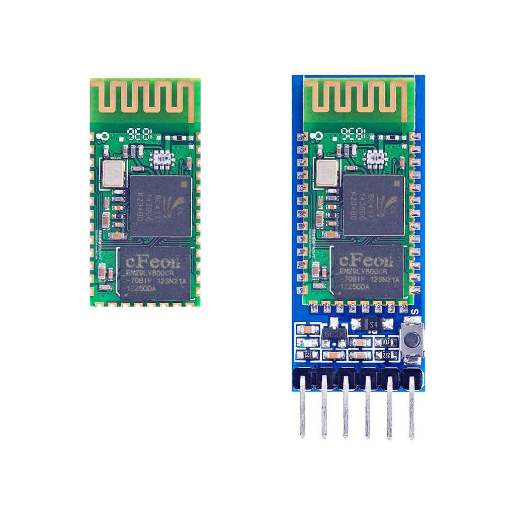
Bare Module vs Breakout Module
The HC-05 is available in two formats: the bare module, which exposes all 34 I/O pins for integration into custom PCB designs, and the breakout board, which simplifies connectivity with standard 6 or 8-pin headers, making it ideal for prototyping with Arduino or ESP32 boards.
Designed for Communication and Control
The HC-05 offers a robust set of features that make it ideal for embedded Bluetooth communication:
- Bluetooth v2.0+EDR (Enhanced Data Rate)
- UART (3.3V TTL)
- Master and Slave Mode support
- Configurable via AT commands
- Baud rates up to 138240bps
- Onboard LED indicators
- 3.3V operation (some breakout boards support 5V)
- Range: Up to 10 meters (unobstructed)
With these capabilities, the HC-05 is perfectly suited for DIY automation, robotics, wireless data exchange, and Bluetooth-connected peripherals.

** The HC-05 pinout is available for download at the end of this post in high resolution – for free!
HC-05 Bare Module – GPIO Fundamentals
The bare HC-05 module exposes all 34 pins and provides maximum control for developers. While only a subset of these pins is commonly used, knowing their function can help unlock the full potential of the module.
Core UART Communication
- TXD – Transmit Data
Sends serial data from HC-05 to the microcontroller. - RXD – Receive Data
Receives serial data from the microcontroller. - CTS / RTS – Flow Control
Hardware UART flow control (optional but useful for stable high-speed communication).

PCM Audio Interface (Advanced)
- PCM_CLK, PCM_OUT, PCM_IN, PCM_SYNC
Support Pulse Code Modulation for audio data. Rarely used in DIY projects, but essential in voice transmission applications.

General Purpose Analog I/O
- AIO0, AIO1
Programmable analog pins for special use cases.

Programmable Digital I/O (PIO)
- PIO0 – PIO11
Multifunction pins used for device status, user-defined I/O, or internal functions like LED indicators and the AT mode trigger.- PIO8 / PIO9 – Typically control status LEDs
- PIO11 – Connected to the KEY input to toggle AT mode

Power & Reset
- VCC – 3.3V power input
- GND – Ground
- RESET – Active low; resets the module
- 1V8 – 1.8V output from internal regulator (for reference use only)

USB and SPI Interface
- USB_D+ / USB_D- – For direct USB interfacing (rarely used without custom drivers)
- SPI_CSB, MOSI, MISO, CLK – Expose the internal SPI interface, primarily for factory programming

Quick Reference Table – HC-05 Bare Module Pinout
| Pin | Name | Function | Notes |
|---|---|---|---|
| 1 | TXD | UART Data Output | Connects to RX of microcontroller |
| 2 | RXD | UART Data Input | Connects to TX of microcontroller |
| 3 | CTS | UART Clear to Send | Optional |
| 4 | RTS | UART Request to Send | Optional |
| 5 | PCM_CLK | PCM Clock | For audio applications |
| 6 | PCM_OUT | PCM Audio Output | |
| 7 | PCM_IN | PCM Audio Input | |
| 8 | PCM_SYNC | PCM Sync Signal | |
| 9 | AIO0 | Analog Input/Output | User-defined |
| 10 | AIO1 | Analog Input/Output | User-defined |
| 11 | RESET | Reset Input (Active Low) | Resets the module |
| 12 | VCC | Power Supply (3.3V) | Use 3.3V only |
| 13 | GND | Ground | |
| 14 | 1V8 | 1.8V Regulator Output | Not for powering external devices |
| 15 | USB_D- | USB Data Minus | Advanced use |
| 16 | SPI_CSB | SPI Chip Select | Factory programming |
| 17 | SPI_MOSI | SPI Data In | |
| 18 | SPI_MISO | SPI Data Out | |
| 19 | SPI_CLK | SPI Clock | |
| 20 | USB_D+ | USB Data Plus | Advanced use |
| 21–22 | GND | Additional Grounds | |
| 23–34 | PIO0–PIO11 | Programmable I/O | Includes KEY input (PIO11) |
HC-05 Breakout Module – Simplified Pinout
For beginners or rapid prototyping, the breakout module simplifies things by exposing only essential pins via a standard 6- or 8-pin header.
| Pin | Name | Description |
|---|---|---|
| 1 | EN / KEY | Enter AT Command Mode — pull HIGH during power-up |
| 2 | VCC | 5V or 3.3V input depending on board design (check carefully) |
| 3 | GND | Ground connection |
| 4 | TXD | Data output to Arduino/ESP (connect to RX) |
| 5 | RXD | Data input from Arduino/ESP (connect to TX) |
| 6 | STATE | High when connected to a Bluetooth device, Low when disconnected |

⚠️ NOTE: RXD is not 5V-tolerant on most modules. Use a voltage divider or logic level shifter when using 5V boards like Arduino Uno.
AT Command Mode
AT command mode allows configuration of the HC-05 — baud rate, device name, master/slave mode, and more.
- Activate AT Mode: Hold KEY pin HIGH while powering the module.
- Exit AT Mode: Power cycle the module without holding KEY.
AT commands are sent over the serial connection. Ensure correct baud rate (usually 38400 for AT mode).
Typical Applications
- Wireless Serial Communication: Replace wired UART links with wireless ones.
- Home Automation Projects: Control relays or devices via Bluetooth apps.
- Custom IoT Interfaces: Use the HC-05 as a simple interface between sensors and a phone.
- Robotics: Remote control of motors or direction via Bluetooth gamepads or apps.
Best Practices and Common Mistakes
To get the most out of your HC-05 module:
- Don’t connect RX directly to 5V logic without a level shifter.
- Use EN/KEY correctly to toggle AT mode.
- Avoid exceeding 3.3V on bare modules.
- Check LED blink patterns for connection status.
- Use debounce logic when driving the HC-05 from buttons.
Programming the HC-05
Unlike the ESP32, the HC-05 is not programmed with code — it is configured using AT commands via a serial terminal.
Common Tools:
- Arduino IDE Serial Monitor
- TeraTerm / PuTTY
- Serial Bluetooth Terminal (Android)
Basic Setup:
- Connect RX, TX, VCC, GND to your microcontroller.
- Use a serial terminal to send AT commands.
- Configure baud rate, device name, and pairing mode.
Conclusion: Simple, Reliable, Wireless
The HC-05 is a classic Bluetooth module that continues to power thousands of wireless microcontroller projects worldwide. Its blend of simplicity and versatility makes it ideal for both beginners and experienced developers. Whether you’re prototyping with Arduino or integrating into a custom board, understanding the pinout of the HC-05 unlocks a world of wireless potential.
Download the HC-05 pinout here in high resolution – for free*!
* Free to use under the MIT license — attribution is required.