
Reference
The Complete Guide to the BH1750 Digital Light Sensor
The BH1750 digital ambient light sensor: real specifications from the ROHM datasheet, pins, I2C addresses, all modes and commands, very bright and very dark light, code and the traps that give wrong lux values.
- 1 to 65535 lx
- I2C 0x23 or 0x5C
- 2.4 to 3.6 V chip supply
- Direct lux output
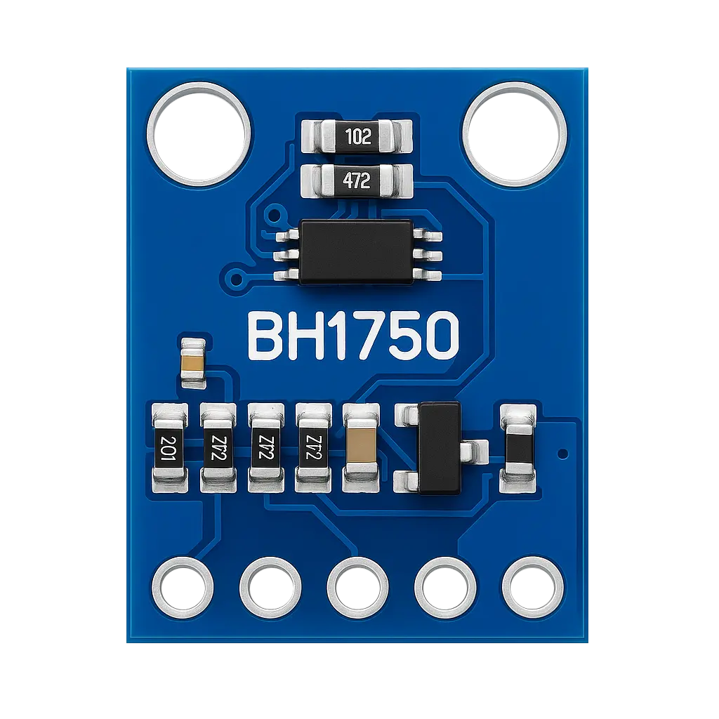
The BH1750 is a small digital ambient light sensor from ROHM that reads light directly in lux over I2C. There is no analog signal to scale, no calibration curve and no photoresistor guesswork: you send a command, wait about 120 ms, and read a 16-bit value. It is used for automatic lighting, weather stations, screen backlight control, greenhouses and anywhere you want to know how bright it is.
This guide covers the real specifications from the ROHM BH1750FVI datasheet, the pins of the common breakout, the two I2C addresses, all measurement modes and their commands, the measurement time register for very bright or very dark light, wiring, code, and the traps that give wrong lux values. Breakout boards differ from seller to seller, so check the labels on your own board.
What is in the chip
The BH1750FVI is a digital ambient light sensor IC from ROHM Semiconductor. A photodiode, an amplifier, an ADC and a small logic block are in one tiny package. The spectral response is close to the human eye, and the sensor has little dependence on the type of light source (daylight, incandescent or fluorescent lamps), which is why you can read the number as a real lux value after dividing by 1.2.
| Item | Value |
|---|---|
| Sensor | Photodiode with built-in ADC and logic |
| Output | 16-bit lux value over I2C |
| Range | 1 to 65535 lx, and 0.11 to 100000 lx when you change the measurement time register |
| Resolution | 0.5 lx, 1 lx or 4 lx, depending on the mode |
| Spectral response | Close to the human eye |
| Interface | I2C, up to 400 kHz, two addresses |
| Package | Very small 6-pin SMD package |
Source: ROHM BH1750FVI datasheet (2011).
Getting started
Specifications
Sensor chip
| Supply voltage (VCC) | 2.4 to 3.6 V, 3.0 V typical |
| Supply current | 120 µA typical (190 µA max) while measuring at 100 lx |
| Power-down current | 0.01 µA typical, 1 µA max |
| Measurement accuracy | 0.96 to 1.44 times, 1.2 typical: divide the raw value by 1.2 to get lux |
| Dark reading | 0 to 3 counts at 0 lx |
| Resolution | 0.5 lx (H-resolution mode 2), 1 lx (H-resolution mode), 4 lx (L-resolution mode) |
| Measurement time | 120 ms typical and 180 ms max (H modes), 16 ms typical and 24 ms max (L mode) |
| I2C address | 0x23 when ADDR is low, 0x5C when ADDR is high |
| ADDR levels | High above 0.7 × VCC, low below 0.3 × VCC |
Breakout board
| Supply | Many breakouts have a regulator and take 3.3 to 5 V, but check yours |
| Pins | VCC, GND, SCL, SDA and ADD (and sometimes DVI, the logic supply) |
| Size | Not given. Measure your own board |
Source: ROHM BH1750FVI datasheet (2011). The breakout data differs per seller.
Dimensions
The chip is a very small SMD package, a few millimetres across. The breakout board comes in many sizes, so measure your own before you design a case. The sensor window is on the top side: put a clear window above it and keep the window clean, and keep the board out of shadow from the case.
Source: ROHM BH1750FVI datasheet. The board size is not given.
Pins
| Pin | Type | Function |
|---|---|---|
| VCC | Power | Supply. 2.4 to 3.6 V for the chip, 3.3 to 5 V on boards with a regulator |
| GND | Power | Ground |
| SDA | I2C | Data |
| SCL | I2C | Clock |
| ADD / ADDR | Input | Low (or open on most boards): address 0x23. High: address 0x5C |
| DVI | Power | Logic supply of the chip. On a breakout it is tied to VCC. It must be powered together with VCC |
The order of the pins differs between boards, so read the print on yours.
Source: ROHM BH1750FVI datasheet, pin functions.
Wiring
| BH1750 pin | ESP32 | Arduino Uno / Nano | Raspberry Pi |
|---|---|---|---|
| VCC | 3.3 V | 3.3 V | 3.3 V (pin 1) |
| GND | GND | GND | GND (pin 6) |
| SDA | GPIO21 | A4 | GPIO2 (pin 3) |
| SCL | GPIO22 | A5 | GPIO3 (pin 5) |
| ADD | Open or GND (0x23), 3.3 V (0x5C) | Open or GND, or 5 V | Open or GND, or 3.3 V |
The chip itself takes 3.6 V at most. A breakout with a regulator may also have pull-ups to its own supply, so run it at 3.3 V on a 3.3 V microcontroller.
Software setup
| Platform | What to do |
|---|---|
| Arduino IDE | Install BH1750 by Christopher Laws from the Library Manager |
| PlatformIO | Add claws/BH1750 to lib_deps |
| ESP-IDF | Use the I2C master driver and the commands below |
Example code
#include <Wire.h>
#include <BH1750.h>

BH1750 lightMeter;

void setup(){
  Serial.begin(115200);
  Wire.begin(21, 22); // SDA, SCL for ESP32 (use Wire.begin() for Arduino UNO)

  if (lightMeter.begin(BH1750::CONTINUOUS_HIGH_RES_MODE)) {
    Serial.println("BH1750 sensor initialized");
  } else {
    Serial.println("Error initializing BH1750");
  }
}

void loop() {
  float lux = lightMeter.readLightLevel();
  Serial.print("Light: ");
  Serial.print(lux);
  Serial.println(" lx");
  delay(1000);
}
I did not run this sketch on a board, it follows the library example.
Modes and commands
The chip takes single-byte commands. Power it on, choose a mode, wait, and read two bytes. The value divided by 1.2 is the light in lux.
| Command | What it does |
|---|---|
| 0x00 | Power down |
| 0x01 | Power on, waiting for a command |
| 0x07 | Reset the data register (only works in power on mode) |
| 0x10 | Continuous H-resolution mode, 1 lx, about 120 ms |
| 0x11 | Continuous H-resolution mode 2, 0.5 lx, about 120 ms |
| 0x13 | Continuous L-resolution mode, 4 lx, about 16 ms |
| 0x20 | One-time H-resolution mode, 1 lx. Powers down after the measurement |
| 0x21 | One-time H-resolution mode 2, 0.5 lx. Powers down after the measurement |
| 0x23 | One-time L-resolution mode, 4 lx. Powers down after the measurement |
| 0x40 to 0x7F | Change the measurement time register (MTreg), high and low bits |
#include <Wire.h>
#define BH 0x23

void setup() {
  Serial.begin(115200);
  Wire.begin(21, 22);
  Wire.beginTransmission(BH); Wire.write(0x01); Wire.endTransmission();   // power on
  Wire.beginTransmission(BH); Wire.write(0x10); Wire.endTransmission();   // continuous H-resolution
}

void loop() {
  delay(180);                                  // 180 ms is the maximum measurement time
  Wire.requestFrom(BH, 2);
  uint16_t raw = (Wire.read() << 8) | Wire.read();
  Serial.printf("%.1f lxn", raw / 1.2f);
}
The sketch has not been run on a board. The ROHM datasheet recommends the H-resolution mode, because its longer integration time rejects 50 Hz and 60 Hz noise from lamps.
Source: ROHM BH1750FVI datasheet, instruction set.
Very bright or very dark light
The measurement time register (MTreg) changes the sensitivity. The default value is 69 (0100_0101). A larger value makes the sensor more sensitive and the measurement longer, so you can read down to about 0.11 lx. A smaller value makes it less sensitive, so you can read up to about 100000 lx, direct sunlight. You must divide the result by the same factor, and the measurement time scales with it, so wait longer when you raise MTreg.
- Send the high bits with
0x40 | (MTreg >> 5)and the low bits with0x60 | (MTreg & 0x1F). - Then start a measurement in H-resolution mode 2 for the best resolution.
- The BH1750 library has a
setMTreg()function that does all this. - Without this, the reading maxes out at 65535 counts in bright light.
Source: ROHM BH1750FVI datasheet, adjusting the measurement result for the influence of a window.
Getting good readings
- Put the sensor behind a window with care. A cover or a window dims the light, so use MTreg to compensate, or calibrate against a reference lux meter.
- Keep the sensor out of shadow from the case and from your own body when you test.
- Use H-resolution mode for dark rooms and when lamps flicker.
- Use one-time mode for batteries. The chip powers itself down after each measurement.
- Average a few readings if you control a light, to avoid flicker from noise.
- Add hysteresis to an on-off light control, otherwise the light turns on and off at the threshold.
- Mind the lamp type. The datasheet states the reading is nearly the same for incandescent, fluorescent and halogen light, but check an unusual lamp such as an LED or infrared light against a reference.
Real gotchas
- Divide by 1.2. The raw 16-bit value is not lux. The accuracy figure of 1.2 means the raw reading is 1.2 times the real lux. Libraries do this for you, a hand-written driver must too.
- The chip takes 3.6 V at most. Only boards with a regulator take 5 V.
- Wait for the measurement. 120 ms typical and 180 ms at most in H mode. Reading earlier returns the previous value.
- Two addresses, no more. You can put two sensors on one bus (0x23 and 0x5C), but not three.
- The reading saturates at 65535. In bright sun use a lower MTreg.
- One-time mode needs a new command. After each measurement the chip is in power-down. Send the mode command again.
- The ADDR pin must not float on a bare chip. Connect it to GND or VCC, or the address is not stable.
- Not a spectrometer. The sensor measures visible light, not UV or infrared.
Compared with other light sensors
| Sensor | Output | Good for | Weak point |
|---|---|---|---|
| BH1750 | Visible, digital lux | Simple, calibrated | 65535 lx without MTreg |
| LDR (photoresistor) | Analog | Very cheap | Not calibrated, slow, nonlinear |
| VEML7700 | Digital lux | Wider range | Another library |
| TSL2561 / TSL2591 | Digital lux | Dual channel | More complex |
The numbers for the other sensors are general knowledge and not from a datasheet read for this guide. The VEML7700 appears in the older version of this guide for readings above 65 klux.
What to build with it
The BH1750 is simple but powerful. Here are some applications:
- Automatic lighting: Turn lights on/off based on ambient lux.
- Weather station: Measure daylight brightness, log sun intensity.
- Greenhouse / indoor growing: Monitor plant light exposure.
- Battery optimization: Adjust display brightness based on ambient light.
- Solar tracking: Combine with servo motors to align solar panels with light source.
Safety notes
Before you wire anything up
- Keep the chip supply below 3.6 V. Only a breakout with a regulator takes 5 V.
- Check the pin order on your own board before you apply power.
- Never connect the board to mains voltage. Keep it on a low-voltage supply.
- Disconnect the power before you change the wiring.
- A light sensor is not a safety device. Do not use it as the only control of lighting that people depend on for safety.
Conclusion
The BH1750 is an excellent upgrade from a simple photoresistor: a digital lux reading over two wires, with two addresses and several modes. Remember to divide by 1.2, wait for the measurement, and use the measurement time register for very bright or very dark light.
Chip data is from the ROHM BH1750FVI datasheet (2011). The comparison table is general knowledge.
Related
 Reference
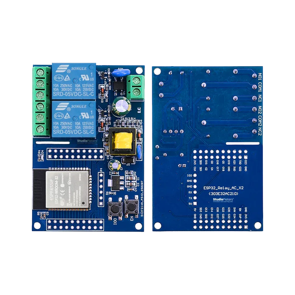
ESP32 Dual Channel Relay Module
The complete pin reference for the ESP32 Dual Channel Relay Module: two 10 A relays, mains power supply, both 2 x 10 headers, the programming header, boot mode and how to flash it safely.
Read more
 Reference
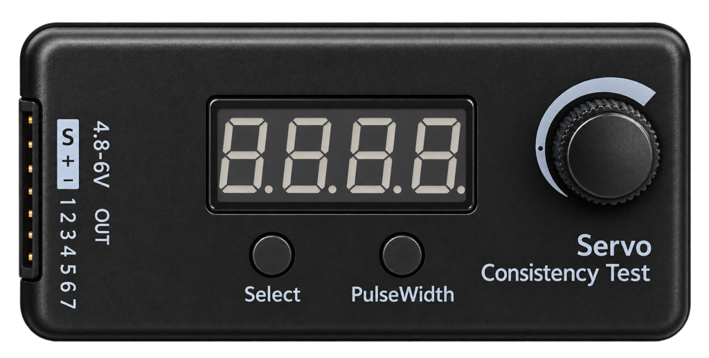
Servo Tester
A small box with a knob that moves a servo without any code: what the modes do, what to look for when you buy one, and how to centre a servo before you fit the arm.
Read more
 Reference
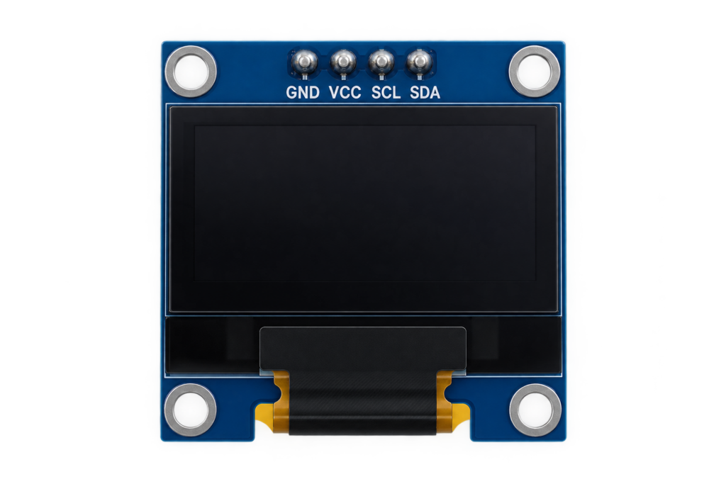
SSD1306 OLED Display
A tiny, self-illuminating I2C display for turning a headless ESP32 project into something readable at a glance. Covers the SSD1306 vs SH1106 offset trap, how the page-based framebuffer works, and avoiding burn-in.
Read more
More guides
Keep building.
From ESP32 HomeKit accessories to Arduino and ATtiny reference guides, there’s more where this came from.
All guides